This thread has been locked.

If you have a related question, please click the "Ask a related question" button in the top right corner. The newly created question will be automatically linked to this question.

INA233: Verification of operation and accuracy

Part Number: INA233

Hello,

Is there a way to properly use calibrated hardware to verify the accuracy of the software readings?

I have tried a few methods and there seems to be a larger then 2% accuracy error between the power reading from the INA233 and the calculated value of the Power based on calibrated DMM readings of voltage and current (using a calibrated probe).

Thanks for the assistance!

Karen

  • Hello Karen,

    Thanks for using the forum to answer your question.

    Question I have is when you are comparing the measurements do you make the current and the bus voltage measurements as well? Is it the current or bus voltage that does not match your measurements. This will help track down the root cause.

    I would assume it is the current but please verify. Also the Rshunt value is it a 1% resistor or does it have a higher accuracy rating. What is your current level and Rshunt you are using. The reason I as is depending on those value we may ask to look at your layout, or how you are connecting to your Rshunt. If Rshunt is very small then you would have to account for errors in the contact resistance. Some resistors have sense pins to decrease this error.

    Are you currently using our INA233EVM for your evaluation. If so can you provided the register information and what was chosen for your calibration Register.
  • Javier,

    Thank you for your quick response!

    When I am comparing the measurements, I made the following measurements at 1A, 10A, and 20.8A:

    DMM HW measurement of VBUS

    SW reading of VBUS

    HW Current probe to scope for current measurement but at an output connect around wires connected to electronic load

    SW reading of Current

    SW reading of Power

    Paper Calculation based on HW Current and Voltage readings

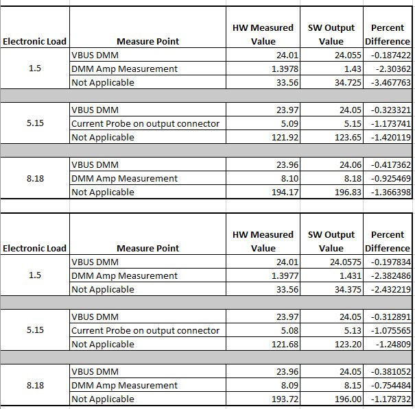
    Below is  a summary of the data from two boards. The current probe for the first table was placed over one wire and the current doubled so that could definitely attribute to the tolerance difference.

    How can I determine, based on calculations and tolerances of the INA233, the tolerance for each measurement I should expect? The sense resistor is a 1% resistor, 2mohm.

    Thank you,

    Karen

  • Karen,

    I believe you are correct about your current measurement from your current probe is not accurate. I would assume it is about placement of the probe.  So there are a couple of items that you can attribute to error in your power measurement. 

    The first of course your Rshunt and its accuracy of it.  Please be aware you may also have to account for temperature variation of the Rshunt depending on how much power it is dissipating. 

    Next lets look at the current error measurement.  There is a calculator on the INA233 product page on the right hand side that can assist with this for your conditions but it is normally about 0.1% gain error.  The calculator adds offset and other conditions.  We have training videos that can help understand these errors.

    Calculations are made and scaled so you have to also insert a value based on your Rshunt value into the calibration register and have limited resolution.  I would assume your Rshunt accuracy would contribute a larger error than the resolution limitation of the Calibration Register and Scaling.

    Next Vbus accuracy is specified at 0.1% gain error +7.5mV offset at room temperature.

    The power calculation is also specified for at 0.2% at room.

    Also you can see there is something in your measurement on Vbus that is different on Vbus for the first board.  Don't know what the cause of that error is.  For the most part you error will come from your Rshunt as it is specified at 1%.

  • Javier,

    For the first board I believe the issue was the issue of a current probe for one wire and doubling the measurement with the assumption that the current was shared equally. The assumption was made based on testing using the current probe but at the time we only had one current probe that could handle the large current. The second board used a current probe that could handle the large current.

    Based on the error spreadsheet at a minimum of 1A I would see about 1.8% for the current reading. I tried changing the resistance based on the 1% value of the shunt and I don't see the kind of fluctuation that I see in the values. I calculated some of the errors on my own to obtain about 1% at 1A. 

    Is the issue I get a setup issue? What else can I check to verify functionality?

    I changed the  measurement to use a DMM to measure the current in the path to see if there is any improvement. There is some consistency between the two boards. The DMM has a 0.3% +2 significant digit resolution on the current measurement. Below is updated data. 

    .

    Thank you,

    karen

  • Javier,

    Just following up.

    Thanks!

    Karen

  • Karen,

    I would assume there is a setup issue.  If you look at your data collected the numbers match from each board very consistent.  Both the HW and SW repeat in both boards but I have some areas you can look into.  What shunt value are you using?

    I would look into why your Vbus changes as you increase your current on your DMM measurement but does not change with the software.  Are your measurements made using the exact same nodes?  GND and VBUS pins on INA233 should be your reference points.  Is there any shift in the ground as you increase your current?  When comparing this you can measure the VBus voltage.  If you are measuring with the current measurement in series you are adding a resistance and you can be changing the voltage based on the current draw as well.

    When using your Electronic load that may be a better accuracy than your DMM.  Look at the specifications of the Electronic load and compare the accuracy vs your DMM.  Most DMM do not measure such large currents.  Are you measuring the current directly and at the same time as the software from the INA233.  May I ask what DMM you are using for this measurement?

    With that being said there is a big difference at the 1.5A measurement.  Is there some leakage somewhere?  Most electronic load should be able to pull the 1.5A with not such a large error.

  • Javier,

    I measure at VBUS but through test points connected to that plane.

    The DMM (Fluke 77) I was using for this measurement has a +/- 0.3% +1 significant digit tolerance. However, it may be the resolution causing what you see. I will retest with a DMM that has more digits.

    I agree with the resistance being affected by using the current measurement function of the DMM. I used short (2") length wires but connect to the DMM. I will check the Electronic Load readings vs the SW and see if that seems to align better without the DMM in the path.

    I am using a 600W electronic load. The specifications indicate 0.3% +30mA tolerance. The DMM can measure up to a max of 10Amps. The accuracy is 0.3%+2 significant digits. (Fluke 289) I am measuring the current as "at the same time" as possible. Unfortunately, the SW output is a command through a terminal.

    I will redo some measurements with an updated setup based on your input.

    Something else I have a question on is the total error. Does the input application for the INA233 that exports an error chart and excel of the tolerance in the range of the current measurement for the current readings basically include the errors as explained in the current amplifier video series? I tried to do the calculations separately and cannot get the values as per the TI calculator.

    I want to verify the tolerance at the respective current measurement is a valid expectation.

    Thank you,
    Karen
  • Karen,

    The calculator does an RSS for all the errors.  When making the calculations please compare with RSS if you are not. 

    As you will notice most of the error will change the offset of the device from the videos.  Such as PSRR and CMRR.  This offset error has a bigger influence on currents measured in the lower values.  This is something that is expected.  The value should approach the gain error are you increase our larger currents as the offset voltage plays a smaller part in the error.

    In the INA233 the gain error 's biggest change is due to temperature as you can see the error change as you increase the temperature value. 

    Normally when you are attempting to make measurements we want the equipment to be better than the specification we are comparing too.  You can do other things to make your measurements better like measure your Rshunt and use the value you measured.  This is only if your measurement is better than the accuracy of your Rshunt value.  

  • Javier,

    The measurements with the SW does change throughout. The higher the current the more stable the SW reading is.

    Here are updated values with a DMM with 0.3% accuracy (HP 34401A) measured as close to the VBUS as possible. I used the electronic load current as you suggested for the accuracy comparison. The tolerance of the electronic load is +/-0.3%+30mA. Am I right to conclude that with the tolerance of the eload it would be difficult to determine HW vs SW accuracy? Namely, the current at the maximum or minimum of the tolerance could make this measurement meet the tolerance indicated by the error calculations. From input to output there is an expected 0.0072ohm resistance due to 2x 2mohm current sense resistors and the rds(on) of a FET in the path. Rds(on) is 0.0032ohm and max 0.00352ohm normalized to a temperature rise to 50C on the FET based on the FET. Any other feedback that would help in ensuring there is no HW issue causing the delta from the expected tolerance for the current?

    Thank you,

    Karen

  • Yes. I am using the RSS error that it outputs.
  • Karen,


    Am I right to conclude that with the tolerance of the eload it would be difficult to determine HW vs SW accuracy?

    Yes, you are correct.

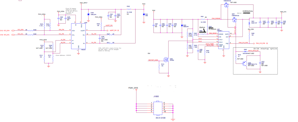
    Is there anyway you can have a schematic of how you have the inputs connected with the fets. Hand drawn should be fine.
  • Javier,

    Attached are the circuits showing the connection to the FET as well as the top layer of the layout for the INA233 to the in rush circuit that controls the FET. This is an 8 layer board. 2oz copper on top and bottom. Internal There are copy of the top planes on the bottom and an internal plane for both P24V and P24V_SYS.

    Look forward to your feedback.

    Thank you,

    Karen

  • Karen,

    I looked at your schematic and layout and they seem fine. The only potential issue I see is the resistance of the R302 being different because of the solder connections. It looks like the connection is done the best way possible.

    To verify this use the accurate 34401 and measure the voltage across the top of R302 when you have current running. Then probe on the input pins to the INA233. You should not see a big difference. Also when probing on R302 change the location on which you probe. If the voltage does not change for any of those measurement you are ok with the layout.

    You still need an accurate current measurement to compare to your INA233 output. You could use the 34401 but it is only limited to 3A I believe.
  • Javier,

    I did as you suggested.

    I put a 1.5amp load on the board.

    I measured 3.011mV on top of R302 and 3.011mV on the pins of the INA233. However, I measure about 100mV more if I measure on the solder pads on R302.The masurement does not change ON R302 but outside of R302 it does.

    Based on your comment, the layout seems to be ok?

    Please advise.

    Thank you!

    Karen

  • Karen,

    Yes. Karen your layout is good. You are measuring the added resistance not on R302 itself. This is good. I believe if you can compare this number to your 34401 you should be good. Please be aware you will have varying resistors and that will be your 1% error unless you get a more accurate resistor but that comes at a cost. Or if you calibrate each resistor which is also at a cost.