A related question is a question created from another question. When the related question is created, it will be automatically linked to the original question.
If you have a related question, please click the "Ask a related question" button in the top right corner. The newly created question will be automatically linked to this question.
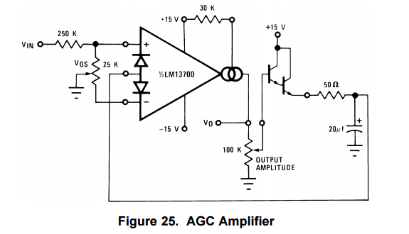
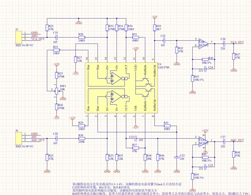
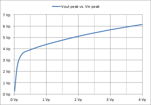
Figure 25 is a complete circuit. The automatic gain is based on this output current formula. VOUT = Iout * Rout
Larger input signals increase the 20uF cap voltage which increases Id current. Increased Id current reduces the gain. So this is a simple compression circuit to increases the dynamic range of input. So a wide input amplitude range becomes a more narrow output amplitude range.
More complicated circuits could record the peak voltage and use an error amplifier the get a fixed peak output voltage. The error amplifier would drive the Iabc current instead of diode bias pin. Loop stability and response time of the automatic gain become side effects to consider.
What is the expected input signal range (voltage & frequency)? Does the DC component of the input signal need to be preserved? What is the acceptable output voltage range?
Many LM13700 applications including this one run in an open loop (no feedback). Therefore it will naturally lack the S/N that high performance op amp will have. In negative feedback op amp circuits, the op amp uses some of its gain to perform the designed function. The remaining op amp gain is used to drive the difference input voltage closer to zero. This greatly reduces non linearities that will be present in the output signal. Conversely, LM13700 is open loop so nonlinearities become part of the signal with no reduction. It is the open loop that is the issue . Closing the loop (adding negative feedback) would fix the problem but it would also negate the variable gain feature of the LM13700.
In addition, the AGC function will also add distortion as the AGC function will have ripple at input frequency and will have distortion when it needs to correct the gain when the input signal changes.
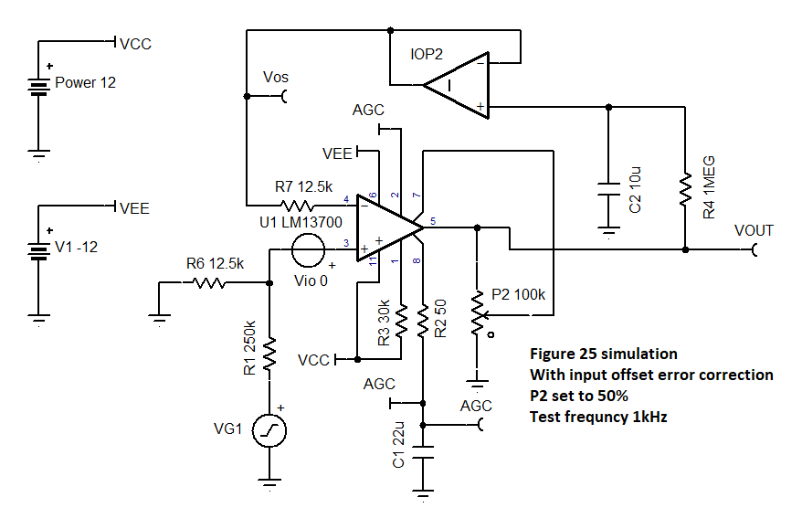
I simulated the figure 25 data sheet design. I did not like that input offset error was such a big factor that had to be corrected manually (with input potentiometer) . .So I added a DC input offset correction circuit (R4, C2, buffer IOP2) to eliminate pot, P1.