This thread has been locked.

If you have a related question, please click the "Ask a related question" button in the top right corner. The newly created question will be automatically linked to this question.

THS4281EVM: This EVM seems to not have schematic attached.

Part Number: THS4281EVM
Other Parts Discussed in Thread: THS4281

Unlike other EVM, THS4281 seems to not have schematic attached.

This is too odd that there is no seperate EVM specification document. Instead, only a layout section in the datasheet is provided.

The EVM still lacks schematic and BOM information which usually can be easily found within other device's EVM specification.

By the way, the schematic shown in the first page of THS4281 datasheet looks wrong. The inverting and non-inverting inputs hooking on the sensing resistor's ends should be swapped.

Could you please help clarify these concerns.

Thanks a lot.

  • Hi Fan,

    if you have a close look at the layout in figure 76 and 79 of datasheet, you will notice that the circuit of EVM is extremely simple. And the datasheet contains enough information to find out what sort of resistances are suited for this circuit. See figure 68 and 69 of datasheet.

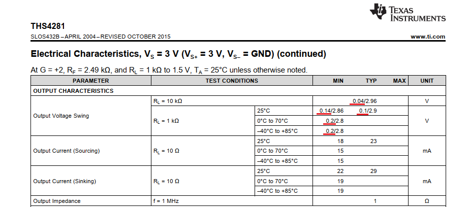
    No, the schematic on the first page isn't wrong. As no OPAmp can fully swing with the output to the negative supply rail, the output of THS4281 emits VBAT/2 when measuring zero current and the output voltage decreases when the measuring current increases.

    Kai
  • Hi Kai,
    Thanks for the response.
    We'd like to quickly start to evaluate the chip within our application context that needs minimum change to the original configuration.
    Nevertheless, a concrete schematic and BOM will be very helpful, otherwise we have to reverse-engineer the circuit including both circuit structure and component value, let alone the rating in details.
    As for the schematic, do you notice the equation Vout=Isense on the output side ?
    Could you help derive this equation based on such configuration?
    Thanks again.

  • Hi Fan,

    yes, I did notice the eqution "Vout = Isense". But I think it is meant in the way I described, because it's impossible for the THS4281 to emit 0V output voltage for Isense = 0A:

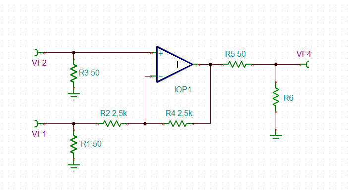
    The schematic of EVM is not identical with the schematic on the first page of datasheet. I think it's more like that:

    Kai

  • Hi Fan,

    I will look to see if I can find you a BOM and/or schematic for you for the EVM.

    Thanks!
    -Karan