This thread has been locked.

If you have a related question, please click the "Ask a related question" button in the top right corner. The newly created question will be automatically linked to this question.

op amp full wave rectifier output has a significant offset

Other Parts Discussed in Thread: OPA2197

I would like to know the root cause of the op-amp output offset at the following circuit. 

The following is a circuit to measure the AC current by using a current transformer (not included in the schematic).

IC133 is a full wave rectifier. C174 is used to block the DC component in signal.

Figure 1

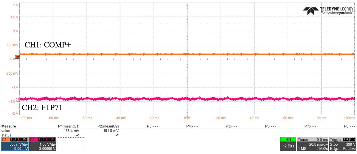
For this circuit, there is a significant output offset on FTP47 or FTP71 about 1V and it is noisy, refer Figure 2.

Figure 2

If the R186, R189, R191, R197 reduced from 100kOhm to 20kOhm and R185 removed, the output offset is decreased significantly, Figure 3.

Figure 3

  • Hi Yee,

    yes, the resistances are much too high for my taste. Decreasing them to 10k sounds good. Why not omitting R191 at all?

    OPamp rectifier circuits often profit from a phase lead compensation. Otherwise, during the diodes' on-off-switchings considerable ringing can be generated. I would mount a 10...22p cap from the -input to the output of each OPAmp. You could also insert a small isolation resistance of 22...100R into the rectifier outputs before connecting them together.

    By the way, there are better full-wave rectifier circuits then the shown one:

    tidu030.pdf

    Kai

  • Hello Yee,

    Resistors produce thermal noise that increases with resistance. The mean-square open-circuit voltage (e) across a resistor (R) is:

    en = √ (4kTKRΔf)      

    where:

                 TK is Temperature (ºK)

                 R is Resistance (Ω)

                 f is frequency (Hz)

                 k is Boltzmann’s constant  (1.381E-23 joule/ºK)

                 en is volts (VRMS)

    To convert Temperature to Kelvin  TK (ºK) = 273.15 ºC + TºC   

    A 100 kilohm resistor produces approximately 40 nV/√Hz of thermal noise density at 25 ºC, and that drops to about half that level for a 20 kiloohm resistor. The Op amp circuit configurations affects how the resistor's contribute their noise. For example, R191 contributes the full noise because it isn't shunted by any other resistors. Where as R185, R186 and R189 is a series-parallel combination and the noise in that portion of the circuit is based on the equivalent resistance. The point here is that the 100 kilohm resistance are producing noise that is dominating the Op amp noise. Reducing their resistance values should lower the noise.

    Regarding the voltage offset the OPA2197 input currents flow through the various resistors. If the resistance values are high such as 100 kilohm greater voltage drops will result then when the resistances are lower. Again, reducing the resistor values should help reduce the contribution to voltage offset contributed by input bias current flowing through the resistances.

    Kai's recommendation of the TI Precision Design, "Precision Full-Wave Rectifier, Dual-Supply" is a good recommendation:

    http://www.ti.com/lit/ug/tidu030/tidu030.pdf

    As you can see from the report very good performance was achieved.

    Regards, Thomas

    Precision Amplifiers Applications Engineering

  • Thanks for Kai provided a good recommendation. That is an excellent and good performance circuit in tidu030.pdf that I haven't seen before.

  • Thank for providing a root cause.