This thread has been locked.

If you have a related question, please click the "Ask a related question" button in the top right corner. The newly created question will be automatically linked to this question.

OPA2189: OPA2189 Open Loop Gain

Part Number: OPA2189


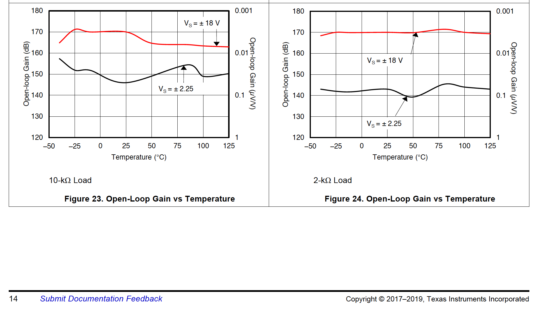
Hi - in looking at Figures 23 and 24 of the OPA2189 datasheet, it appears that when operating with +/-18V supplies, the open loop gain is higher with a 2k load vs. a 10k load. Is that true for the family or was that just with one part tested? I'm trying to figure out how to maximize this spec. Also, do you have a graph showing open loop gain distribution for a bunch of parts at 25C (e.g., similar to what's often done with offset voltage)? And finally, is this the best amplifier you have for this spec? Thank you.

  • Hey Doug, 

    Assuming for a moment you are trying to make the most accurate unity gain buffer you can, there is another term to consider - the CMRR. 

    Think of that as another gain error where an input uV/V type of error can be imputed to that spec. Oddly, I discovered there is some ambiguity on the polarity of this error term. Some folks (and models) seem to treat this an expanding gain effect, while others show it contracting - I have even seen some older models get updated to reverse this polarity. Got into this kind of as a side note to discussing what CMRR is for a current feedback device where this article shows an easy sim approach for either. 

    https://www.planetanalog.com/author.asp?section_id=3404&doc_id=565037&page_number=1

    So like your Aol, it would be interesting to see the ATE histograms for CMRR in a uV/V sense with polarity correctly reported. 

  • Hi Doug,

    The OPA2189 has the highest listed, typical open-loop gain (Aol) of any of our Precision Amps Op amps. Most of our Op amps have a high typical Aol in the range of of 130 to 140 dB.

    Normally, we would expect the 10 k load open-loop gain to be higher than with a 2 k load, but that doesn't appear to hold for the OPA2189 (VS = ± 18 V) case at higher temperatures. Do keep in mind that the the input voltage level is in the range of 5 to 10 nV for the 160 to 170 dB Aol shown in the graphs, and the 0.1 to 10 Hz noise is in the 50 nVpk range (datasheet Fig. 17). Therefore, the Aol is being extracted under the conditions where the noise is significantly higher than the input voltage. Multiple devices are used and the measurements use very high averaging because of the noise. Likely, there is a higher order factor at work within the Op amp, or the measurement system, that is resulting in the somewhat lower than expected Aol for the 10 k load, higher temperature condition.

    Regards, Thomas

    Precision Amplifiers Applications Engineering

  • Hi Michael, thanks for your feedback. I'll be using this for gain where the common mode range is fairly fixed.

  • Hi Thomas,

    Thanks for clarifying about the load and that this is the highest AOL precision amplifier. I'll be taking some gain of a small (low bw) signal, so the open loop gain is important to me. However, if I get 170dB, I'll admit that other items will be an issue (I will be filtering to reduce noise). Though, I'm most worried about the140dB min AOL specification over temperature, thus was wondering what percentage of parts ever hit that (thus the request for the histogram).

    Regards,

    Doug

  • And checking the CMRR in the model shows it is an expanding gain model (the Aol effect is contracting, so in theory this conteracts that?). This 10V CM swing at theV+  input generates a 5.06uV error swing in this sim, or a 126dB CMRR. quite a bit lower than spec and is the polarity really expanding. 

    here is this file, It is possible at this very low level of error, the DC V+ input impedance is causing part of this error - inserting a dependent source from the 1kohm to ground would isolate on that. I did try that, no change. 

    OPA189 CMRR input error extract.TSC

  • So at least at the model level, the expanding CMRR effect overrides the Aol LG contraction effect and actually shows increased gain from 1.000 in a unity gain follower, You can't get enough digits to see that with the markers, but you can dump out to excel and see it. Using this simple set up, 

    here is a compressed data record just looking at the final values on each polarity, and yes the gain simulates to slightly >1.00 (really??). I am pretty sure that is the CMRR error being modeled as an expanding gain effect at a higher level than the Aol/(Aol+1) contraction. Back when I was investigating this for that article, it seemed the transistor level models were normally a contracting effect - which is actually what I would expect. 

  • Incidentally, those 25C min and over temp mins are pretty much always designer delivered over process case and temp sims using the Cadence PDK. Very rarely measured. Those are linked to the physical devices shipped by the wafer level acceptance test sites to the key device specification driving the end product specs. 

  • Michael, thanks for your great support. My question has been resolved.

  • Sure Doug, 

    Did you find it odd that the unity gain buffer actually simulates to be a >1.000 gain?