This thread has been locked.

If you have a related question, please click the "Ask a related question" button in the top right corner. The newly created question will be automatically linked to this question.

LM331: Accuracy in 100Hz to 200Hz

Part Number: LM331

Hi team,

I'm trying to measure the frequency in the range from 100 Hz to 11 KHz. But I need high accuracy in the range from 100 Hz to 200 Hz (± 4 Hz).

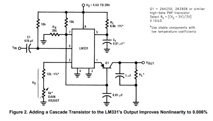
I made "Figure 2" circuit from the application note SNOA734B from TI, which adds a PNP transistor to acts as a cascade in order to improve nonlinearity. It works very well but in low frequencies I get an error of 10Hz and I need more accuracy.

Any idea of how to get less error without adding an active filter?

PS: the output range goes from 0 V to 5 V so when I introduce a 100 Hz signal instead of getting 50 mV I get 55 mV. The voltimeter has an accuracy of 5 uV with 6 1/2 digits so thats not the problem.

  • Hello John,

    SNOA734B is the definitive resource for applying the LM331 as an F-to-V converter. Aside from the inherent accuracy of the LM331 as an F-to-V converter one must consider the input signal to be applied, and the passive components used in conjunction with it and their effects on the frequency accuracy. Regarding the input signal SNOA734B states,"This circuit accepts a pulse-train or square wave input amplitude of 3 V or greater. The 470 pF coupling capacitor suits negative-going input pulses between 80 µs and 1.5 µs, as well as accommodating square waves or positive-going pulses (so long as the interval between pulses is at least 10 µs)." Therefore, be sure that the input signal source meets to these requirements.

    The LM331 requires several passive components to help establish its V-to-F performances. I expect that several of the external components and their inherent accuracy/quality influences the F-to-V accuracy. Figure 2 indicates that several components are specified as needing low temperature coefficients. Additionally, since they appear in the F-to-V design equations they have a directly effect the F-to-V electrical performances. Rt is specified with a 1% tolerance, but consider bumping it to 0.1 % tolerance 6.81 k, or whatever value you are using. Often overlooked in timing functions are capacitor tolerances. Ct has the stable component notation, but nothing is mentioned about its tolerance. I would look for a temperature stable, low tolerance 10 nF capacitor to use for Ct as well. the 1 uF filter capacitor connected to the Q1 collector should be a low-leakage capacitor, and note the temperature stability requirement for RL.  

    One additional note, Rs should be made very close to 14 kilohm. A common application mistake made by users is using a lower value resistor for Rs. Doing so can overload the internal current source.

    Regards, Thomas

    Precision Amplifiers Applications Engineering

  • That was really helpfull, thank you so much.

    One last question, what is the maximum output voltage voltage swing? I´m sourcing it with 5 V

    Thanks,

    John

  • Hi John,

    SNOA734B, in section 3, states "Although the circuit specifies a 15 V power supply, you can use any regulated supply between 4 VDC and 40 VDC. The output voltage can extend to within 3 VDC of the supply voltage, so choose RL to maintain that output range." Therefore, with LM331 Vs set to +5 V the maximum expected output voltage is +2 V.

    Using a low voltage supply for Vs much limits the LM331 output voltage capability. If you can use a higher supply level for Vs, greater the output voltage can be realized providing higher resolution for the application's input frequency range.

    Regards, Thomas

    Precision Amplifiers Applications Engineering