Part Number: INA240
Other Parts Discussed in Thread: EK-TM4C1294XL, TIDA-01159, TIDA-01141
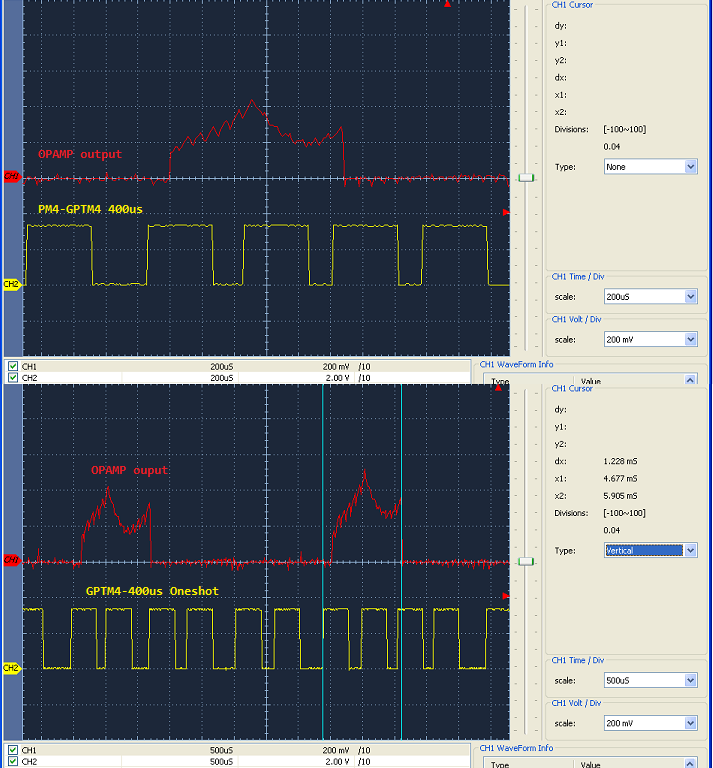
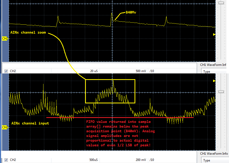
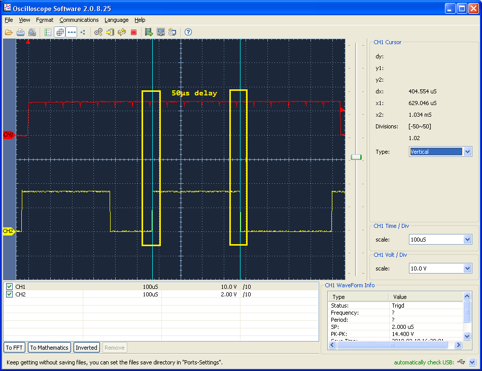
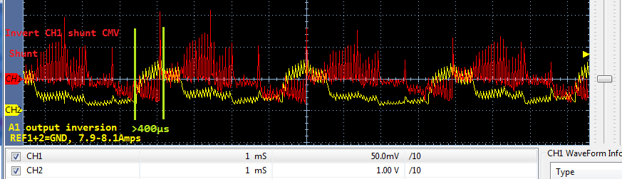
Why does A1 output require a substantially reduced sample blanking time, well below 2x Nyquist sample frequency? The fastest Nyquist rate sample frequency (4.1KHz) possible via 2mohm shunt, 20KHz PWM signal, low side monitor is 240us @2MSPS via TI 12 bit MCU embedded ADC. Any attempt to sample the A1 output signal at a faster Nyquist frequency or rate just above 9.6us A1 setting time produces very low sample values and very inaccurate voltage to current conversions.
Attempting to trigger ADC mid PWM pulse width (25us) to sample A1 output simply produces very low and incorrect RMS current measures. I would expect some SNR error from the 12 bit ADC but not to the point it affects the Nyquist sample rate. Supposedly the 240 PWM rejection transient input filters (as is) reduces spurious out of band harmonic signals so PSRR/CMRR remain fairly consistent to datasheet graphs. Please help me to comprehend how simple low side monitor can not achieve excellent results via 12 bit ADC less than 2 inches away from even six 240 buffered signals on the very same PCB circuit. I don't suspect an issue with the 12 bit ADC or software timing since GPIO debug of scope captures remain/are consistent with/to PWM 25us sample points yet very low value RMS results.