This thread has been locked.

If you have a related question, please click the "Ask a related question" button in the top right corner. The newly created question will be automatically linked to this question.

OPA656: Transipendance circuit

Part Number: OPA656

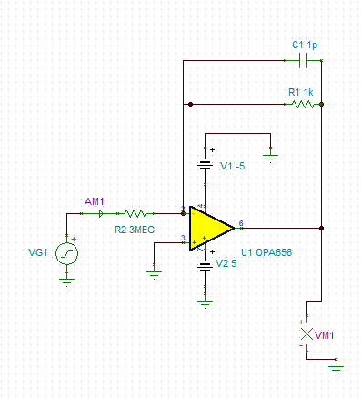
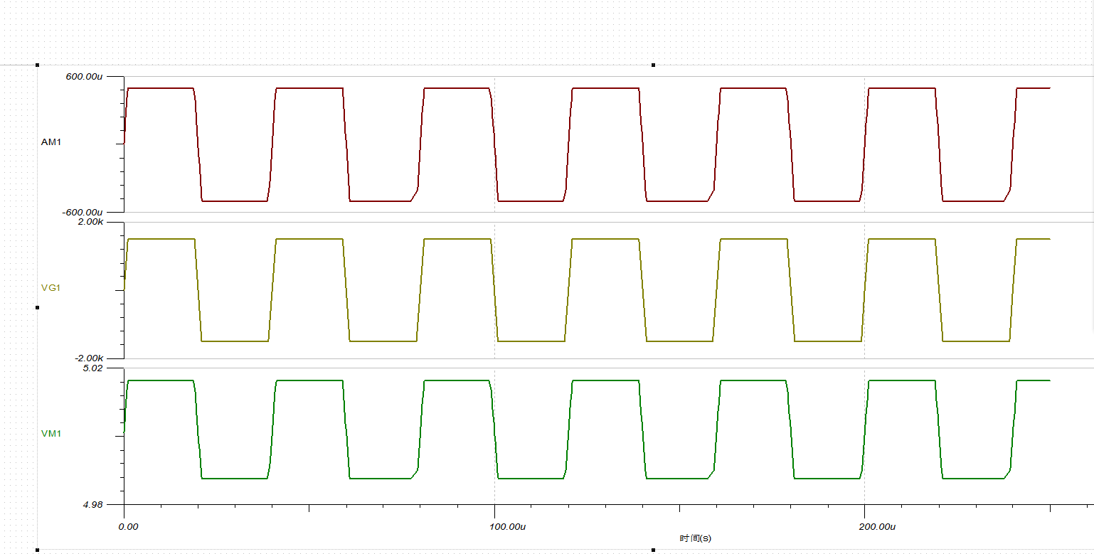
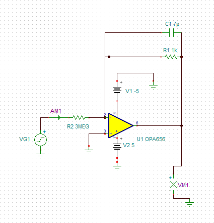
Hello everyone .I design a transipendance circuit to convert 0-5mA current into 0-5V voltage with OPA656. The signal frequency is about 10KHZ. The feedback resistor is 1KΩ.  I try to use a 1pF and 7pF capacitance as  the feedback capacitance respectively , but the effect is not good, there is signal attenuation .The simulation results by Tina  are as follows.  So what  value of the feedback capacitor shouldbe selected?

  • Normally, a current source would have that 3Mohm in shunt, not series. Keeping that 3Mohm in series with a 1mA source implies a 3kV on the source!! Also, 

    1. You cannot set the feedback C with the source C

    2. You cannot swing 5V out on +/-5V supplies - there is some output headroom required. 

  • Dear Michael Steffes:

                       Thanks for your reply.    

           First ,actually, R2 is the equivalent resistance of a pipe filled with water.

           And the source is a signal generator that produces a ±5V square wave signal.    See Figure 1 for details.

    Second , according to the recommended OPA656 transimpedance op amp circuit design, 《Transimpedance Considerations for High-Speed Amplifiers》,the transimpedance op amp circuit requires a feedback capacitor.  so why can't the feedback capacitor C be set with the source C ?         See Figure 2 for details.

    Third,I redesigned the transimpedance op amp circuit according to the OPA656 chip data sheet (Fig 3) and simulated it with Tina, but the effect is still not good, and the signal has different degrees of attenuation on the rising and falling edges.  See Figure 4 ,5 for details.

                                                                                      Figure 1

                                                                                Figure 2

                                                                                    Figure 3

                                                                                                                                                                    Figure 4

                                                                                              Figure 5

  • Well, you are really just doing a large voltage attenuation where I suppose the impedance of the water is in question. 

    1. Can't use +/-15V on the OPA656

    2. Your VG1 looks more like +/-1.5kV

    3. The signal is very slow, you could use a much slower op amp

    4. it looks like the output is following the shape of your current probe signal. Maybe your input is slow?