This thread has been locked.

If you have a related question, please click the "Ask a related question" button in the top right corner. The newly created question will be automatically linked to this question.

TINA/Spice/LMV342: Regarding TINA-TI Spice Model

Part Number: LMV342
Other Parts Discussed in Thread: TINA-TI, , OPA2377

Tool/software: TINA-TI or Spice Models

Hi team,

  Please let me ask you three questions regarding the simulation results of stability(Gain=1)
  and output impedance.
  In addition, I simulated using the following two LMV342 simulation models.

  model1:"LMV342 TINA-TI Reference Design"(www.ti.com/.../toolssoftware)
  model2:"3603.LMV342(RM).TSC"(e2e.ti.com/.../1961828


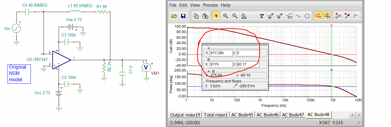
 1. About the stability simulation result(Gain=1).
       The Bode plot of the simulation results of both the models were different from the Bode plot
       on the data sheet. In particular, the phase plot of the model1 is very different.

             *Please see the attached file(Simulation result.xlsx work sheet "Loop Gain")

   Question1)
        Is there any problem with my simulation method?
             *The OPA2377 Bode plot I simulated with the same simulation method for reference
               was almost the same as the Bode plot on the data sheet.

   Question2)
       Which model is correct? Or is there any problem with both of the models?


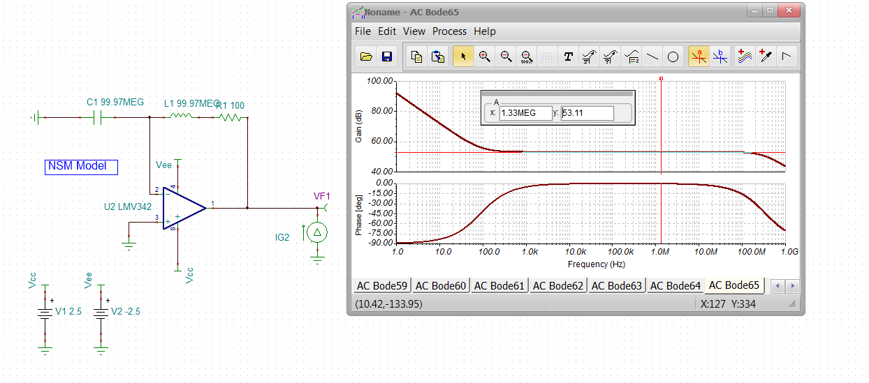
 2. About the output impedance(open loop) simulation result.
       The simulation results were different between the models.

           *Please see the attached file(Simulation result.xlsx work sheet "Output impedance")

   Question3)
        Which model is correct?


 - Simulation result

Simulation result.xlsx


 - Simulation circuit

opa2377_zo.zip

Sincerely,
Tsuyoshi Tokumoto

  • Hi Tsuyoshi,

    Please use the model available at: http://www.ti.com/product/LMV342/toolssoftware. This is the latest updated macro model. The bandwidth of LMV342 is 1MHz, and the model is limited to this bandwidth that's why there is a shoot up in phase plot after 1MHz. I will follow-up with you on why the phase plot starts at a different level compared to that of the datasheet.

    The gain and impedance plot looks good to me. The impedance plot for LMV342 is not available on the datasheet, but this data was collected in lab and the macro model was designed to reflect this behavior. 

    Best Regards,

    Bala Ravi 

  • Bala-san,

      Thank you very much for your prompt reply.
      I will use the latest macro model(www.ti.com/.../toolssoftware)
      for simulating.

      However, I would appreciate it if you could re-check the phase behavior of the latest LMV342 macro model,
      because I am going to simulate LMV342 with several circuit.

      The phase is delayed from around 100kHz on the data sheet, but there is almost
      no change in the phase on the simulation result.
      I am concerned that such differences in phase behavior occurred within the bandwidth.

      In addition, I also attached the file of the simulation result that I simulated the
      stability by Middlebrook method to improve accuracy.

    Simulation result2.zip

     If you have any update, please let me know.


    Thank you and best regards,
    Tsuyoshi Tokumoto

  • Hello Tokumoto -san, 

    I tried the most recent LMV342 TINA model, and it certainly looks like the Aol phase is incorrect. Middlebrook is a good method, I tried a different one and it seems to show no higher frequency poles like the PDS plot shows - and you would expect. I have rotated the sense meter to report phase margin directly, that is what the PDS shows for some odd reason. the phase margin should not be going up like it is at the far right, 

    The most relavent PDS plot is figure 23, this is what you would expect, but the model is missing the higher frequency Aol pole(s). This plot is a little weird in that it is at a gain of 1000 (60dB). So presumeable you would shift the gain up 60dB - there is a risk the phase shift down at higher F is the pole in to the V- input C for whatever R's were being used, if any? Hard to tell for sure, but in any case all VFA have higher order poles in the Aol missing in the current model. 

  • So the TINA V11 library includesthe original national LMV342 model - transistor based. It had trouble running, but if you go into Analysis Options and change to a Davis KLU matrix solver and trapezoidal integration, that usually takes care of a lot of issues, This looks more correct, 80deg phase margin at Aol=0dB, 

     This model file is here 

    LMV342 Aol with NSM model.TSC

  • Hello Steffes-san,

       Thank you very much for your detailed explanations and sharing the new macro model.

       I have been also confused about how to understand the Fig21, 22, 23, 24 (especially Close-Loop Gain=60dB).
       I treated the Figure21 as the Open Loop Gain, but in that case,
       the dominant pole of AoL was located around 3kHz, so AoL became around 60dB.
       The Av(=AoL) was listed as approximately 100dB on the data sheet, so a contradiction occurred.

      On the other hand,the AoL of this macro model(NSM model) was approximately 95dB.
       From the above, I believe this macro model is correct.

       By the way, regarding the output impedance(open loop & closed loop) simulation result,
       the simulation result of this macro model was different from the latest
       model(www.ti.com/.../toolssoftware).

       However, I will simulate other characteristics except the output impedance by
       using this macro model(MSN model).

       Is my understanding reasonable?

       Please let me hear your point of view about my understanding.

    Thank you and best regards,
    Tsuyoshi Tokumoto

  • Yes, your understanding seems correct Tokumoto-san, 

    I did try the open loop Zol sim on the original NSM model, looks pretty reasonable 

    This is dBohms where that midrange flat area is 446ohms, 

    The updated LMV342 model shows a plot in linear ohms of the Zol, different corner frequencies but same shape with a similar midrange flat value, 

    Not sure where this updated data came from, hard to measure, usually comes from designer sims in cadence. 

  • Hello Steffes-san,

       Thank you very much for your prompt reply.
       My doubts have been cleared up!

       I sincerely thank you for your polite and thorough response.

    Thank you and best regards,
    Tsuyoshi Tokumoto

  • You are very welcome Tokumoto-san, 

    I know the product team is working hard to update a lot of these old models to a newer, consistent, template - the current web model shows Paul Goedeke April 3, 2019 using the GWL template. Those are usually very good updates, this one seems to need a little polishing. But you can use the original one from NSM for now - trouble is, those folks are probably gone from a support standpoint. 

    Also, I have noticed some things get changed in these model updates (hopefully to be more accurate) that could then use that same update in the datasheet - that has not been happening, so you end up with confusing mismatches in some cases.