This thread has been locked.

If you have a related question, please click the "Ask a related question" button in the top right corner. The newly created question will be automatically linked to this question.

TL084: tl084

Part Number: TL084
Other Parts Discussed in Thread: SN7407

Dear sir, I am using a circuit which contains Sn7407 followed by pull-up resistor of 1Kohm and the output on SN7407 is going to the input of TL084.TL084 is used as a voltage follower for switching MOSFET with + - 15V.

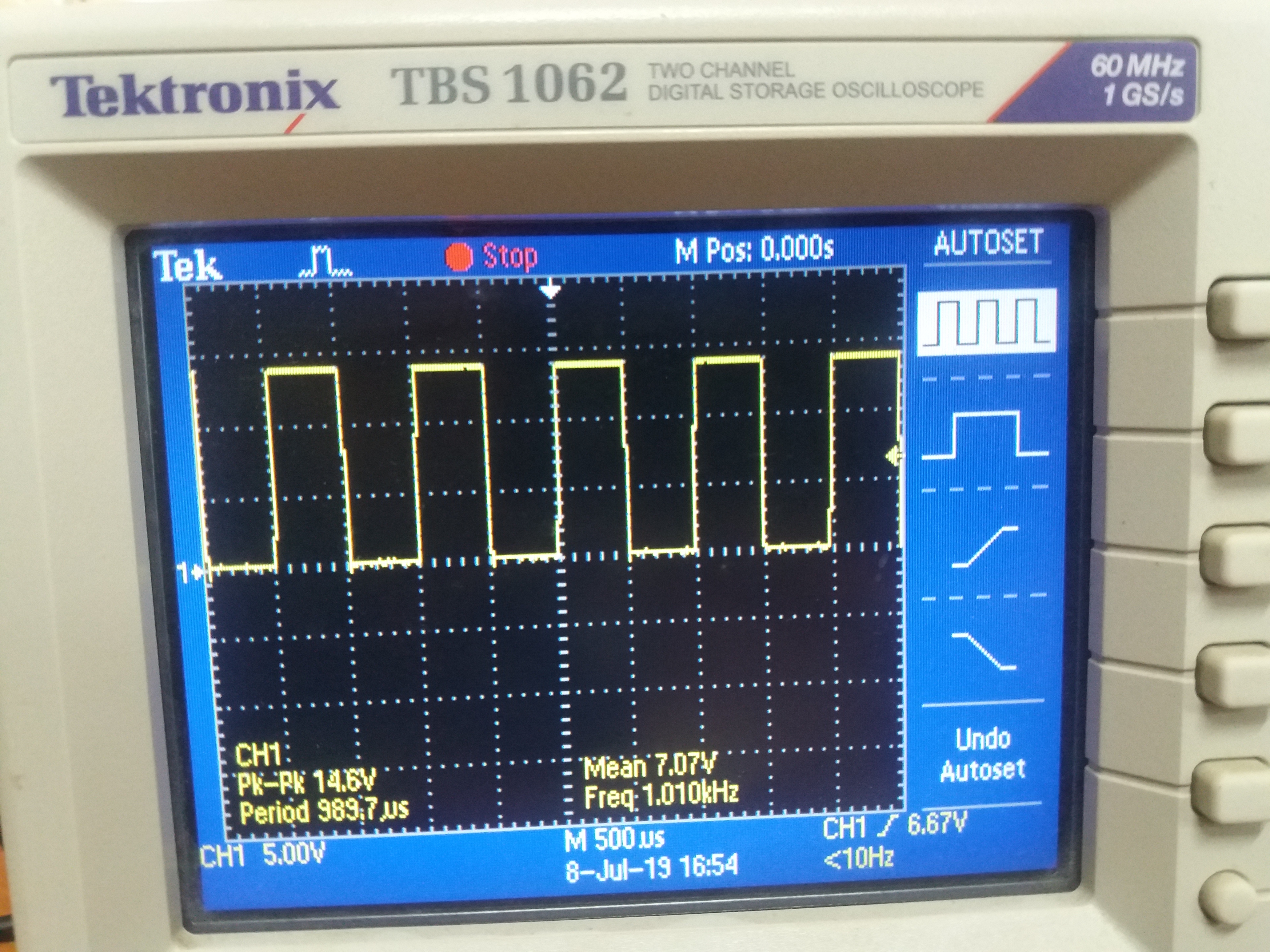
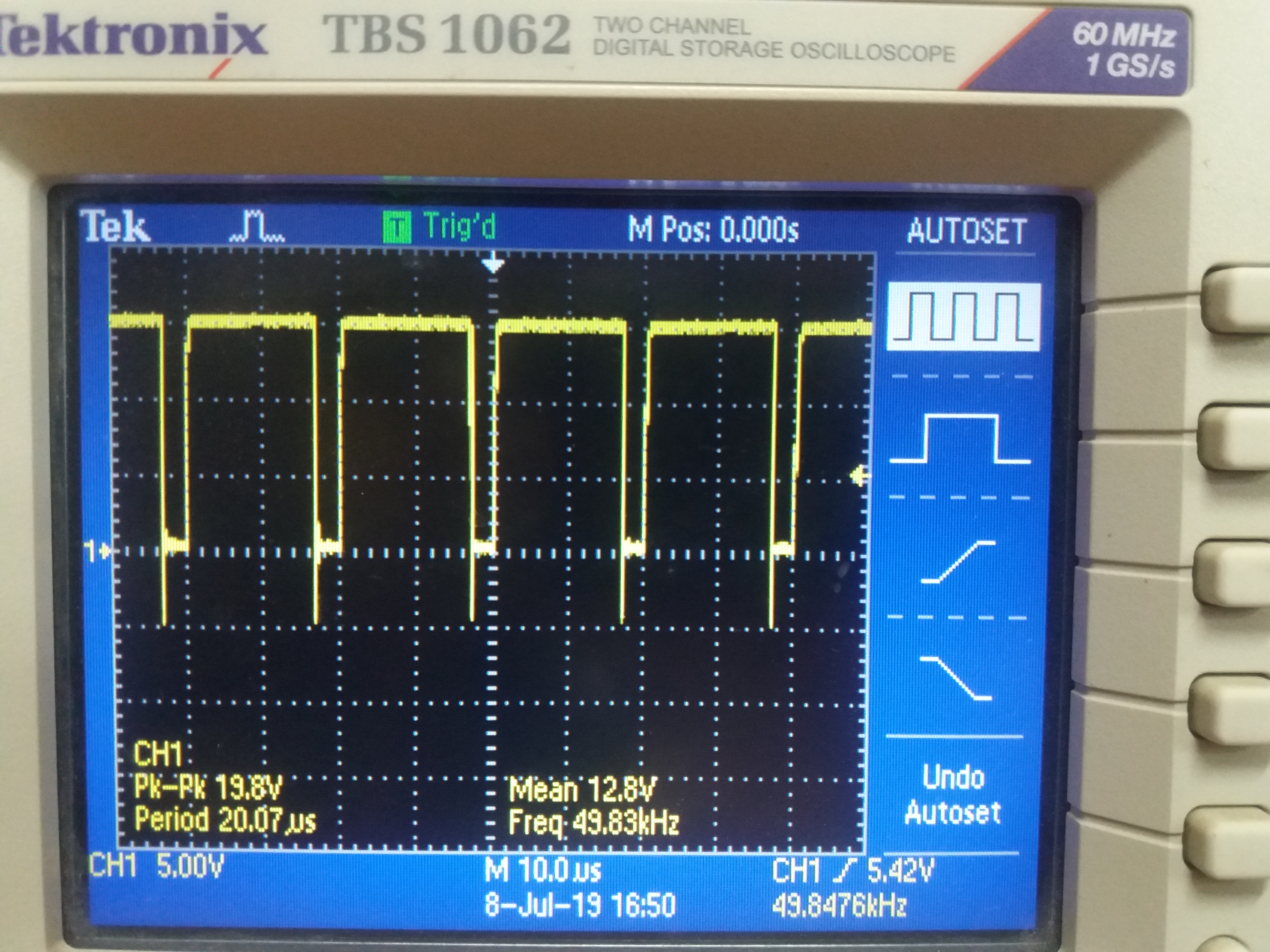
I got good output for 1 KHz frequency but the the output is not good with 50 KHz frequency. 

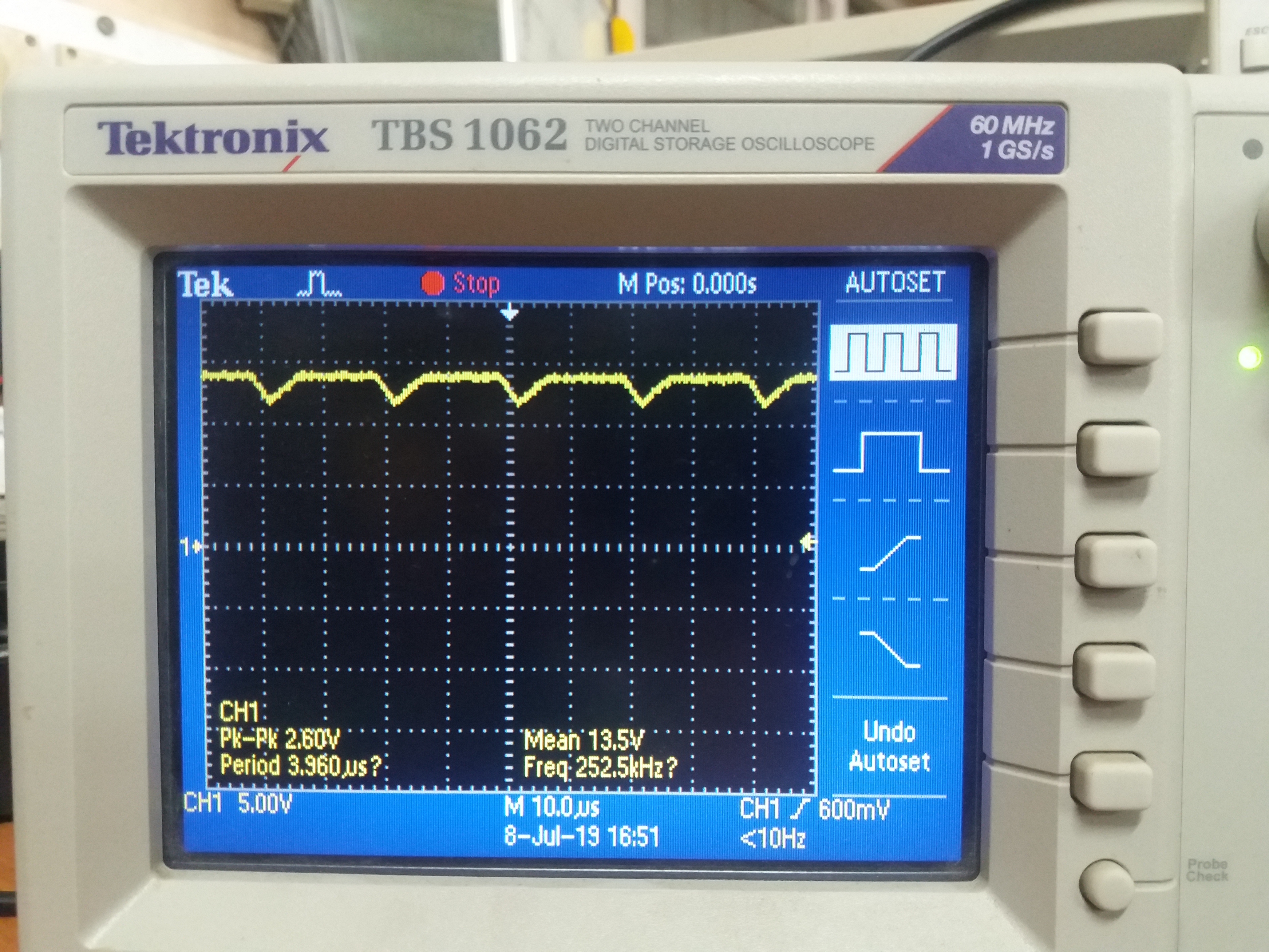
Please have a look at following waveforms: 

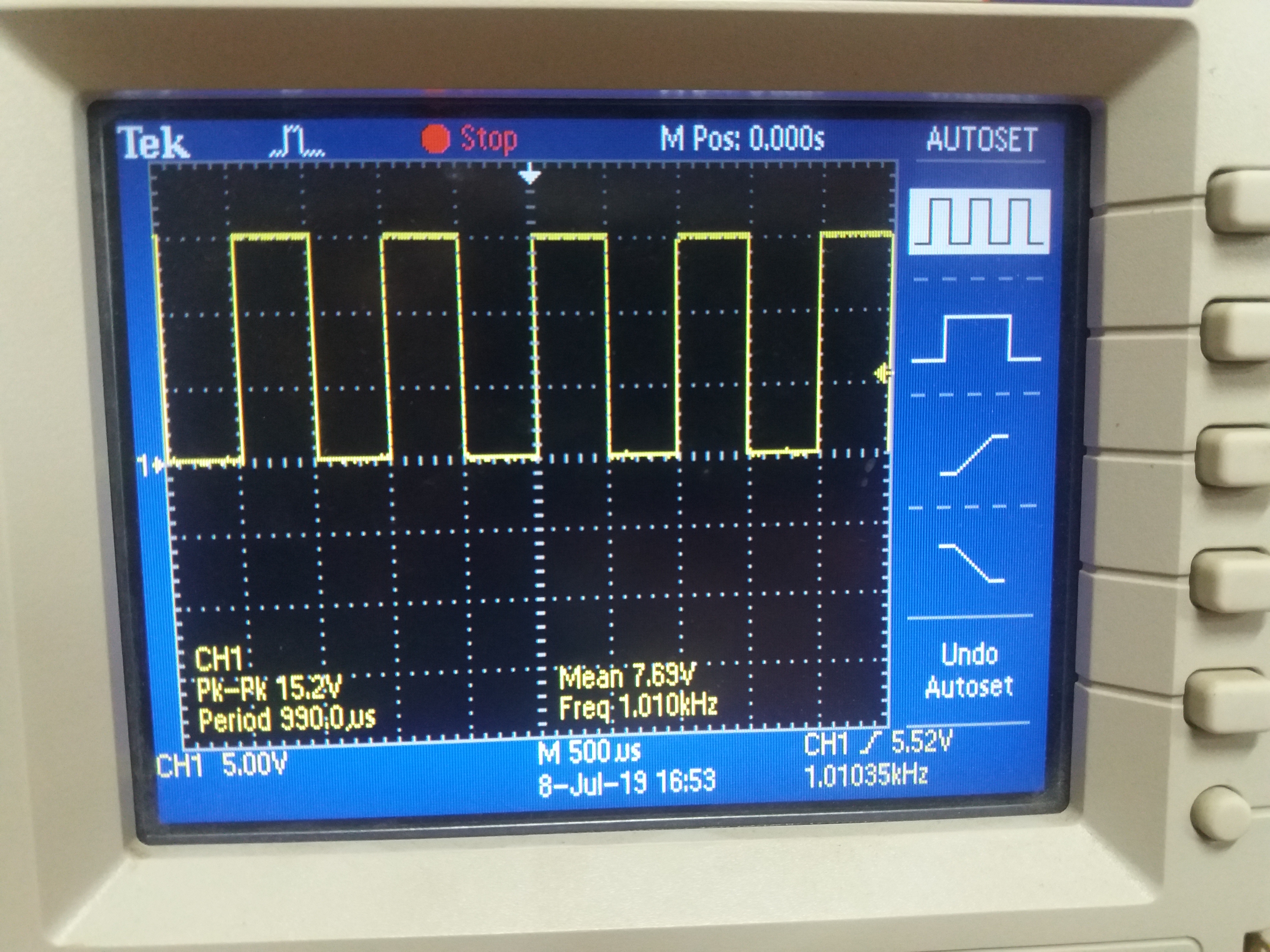
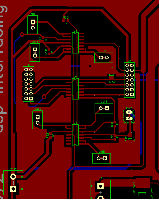
PCB desing is as follows:

  • first two waveforms are input and output to TL084 at 1KHz frequency, while next two waveforms are input and TL084 at 50KHz frequency.

    also in first two waveforms output has 1Volt drop. instead of 15 Volt switching it is giving switching of 14Volts.

  • Hello Hitesh,

    The 15V input is beyond the VOH (voltage high output) of the op amp. Therefore the op amp has a overload recovery time (delay) before the op amp can return to linear operation. Try adding a about 5k pull down resistor to the TL084 input. That will make the input high level 12.5V, the TL084 will remain in linear operation. This will prove or disprove this being the main issue. 

    Would you like a recommendation for a better (faster switching) MOSFET driver. Is required gate voltage always 15V and 0V?  

  • Thanks Ronald,

    I am using the driver which requires switching of +15V and 0V. Can you suggest something how can I use TL084 for this. Can't I operate same PCB for switching of +15V and 0V, by making some small changes in it ?

  • Hi Hitesh,

    As you can see from the datasheet the input common-mode range is between [(Vcc+)-4V to (Vcc-)+4V] and the output voltage swing range for a load of 10kohm is between [(Vcc+)-3V to (Vcc-)+3V]. Since you're using a buffer configuration, your circuit will be first limited by the input common-mode range before the output swing becomes an issue. 

    As you can see from table 6.3 (Recommended Operating Conditions) of the datasheet, the supply voltage range is (Vcc+ - Vcc-) = 15V - (-15V) = 30V. This op-amp does not have a ground pin, so it is okay to use unbalanced power supply as long as you're within the operating ranges of the op-amp. 

    So for your case, to buffer signals between 0V to 15V, you can have power supplies such that Vcc- = -5V and Vcc+ = 20V. 

    Best Regards,

    Bala Ravi