Part Number: INA214
Other Parts Discussed in Thread: INA240
Hi,
Thanks you for your time!
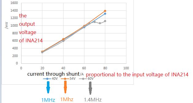
My customer is using INA214 with shunt resistor to measure the output current of their power converter. They found the gain of INA214 abnormal under some case, shown as below.
The Y-axis represents the output of INA214, the X-axis represent the current through shunt resistor, which is proportional to the input voltage of INA214. So that the slope of the curve represents the gain of INA214.
There are three different curves of three colors, meaning three different input voltage working conditions(40V, 54V, 60V), but output voltage and current are totally the same. The only difference of the three colors, blue, orange and gray represent different switching frequency of the power converter. And blue and orange ones are the same, 1MHz, but the gray one is higher, 1.4MHz. The higher frequency only will bring different frequency of common mode noise.
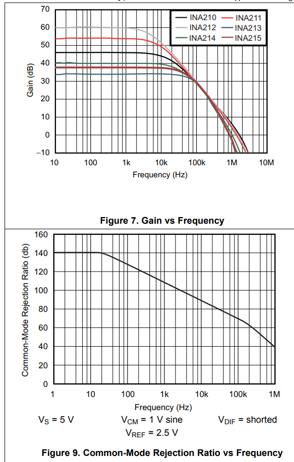
So I wonder if different frequency of common mode noise will affect the gain of INA214?