This thread has been locked.

If you have a related question, please click the "Ask a related question" button in the top right corner. The newly created question will be automatically linked to this question.

INA199: DC current measurement on Neutral Line

Part Number: INA199
Other Parts Discussed in Thread: AMC1300, AMC1302, AMC1301, INA282

Hello,

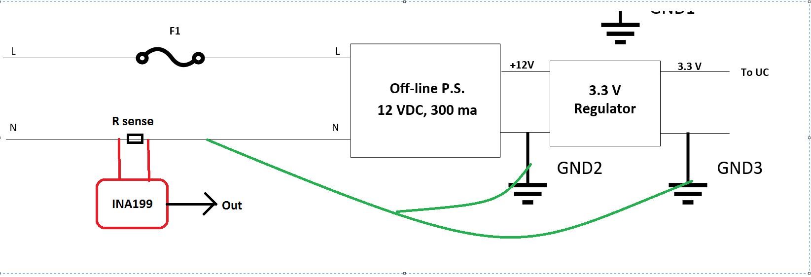
We have AC LED strip in our design, and would like to measure the the current when LEDs are ON/OFF. 

We plan to use INA199 or similar current sense amplifiers on Neutral Line. The measurement current range is from 100mA to 500mA.   

Do you have any recommendation on the device and the circuit design for sensing current on Neutral line ?

If INA199 is good fit then Can I use 10mOhm sense resistor with  200 gain part.

Thanks

Mahesh

  • Hello Mahesh, 

    Thanks for the question. The INA199 (and many other INAs/CSAs) could work as long as its voltage supply (Vs-to-GND) floats with Neutral. This is because of the Absolute Maximum Input Common-Mode voltage rating of -0.1V to +26V.

    The next problem is level shifting the output from LINE to Earth GND or system ground, so some ADC can record voltage measurements.

    One idea is to use some isolated switching power supply to generate the Vs rail for INA199 and then use a voltage isolator for the VOUT signal. You could also do the same thing, but use a digital part and then isolate the digital bus with a digital isolator. A third option is to use a current sense amplifier (CSA) with built in isolation such as the AMC1300, AMC1301, or AMC1302.

    Here is some high-voltage sensing publications you could reference.

    40 V to 400 V Uni-directional Current/Voltage/Power Monitoring Reference Design

    http://www.ti.com/lit/ug/tidu849/tidu849.pdf

    High-voltage, high-side floating current sensing circuit using current output, current sense amplifier

    http://www.ti.com/lit/an/sboa295/sboa295.pdf

    –48-V Telecom Current, Voltage, and Power Sense With Isolation Reference Design

    Sincerely,

    Peter

  • Thank you Peter for quick response.

    In our design, system ground and Neutral line are same. So yes, Voltage supply (Vs to GND) floats with Neutral.

    Micro controller which has ADC also referencing to Neutral line.  In this case can we use INA199  or any other  INAs/CSAs ?

    do we need to add additional Amplifier to increase the INA199 output voltage ?

    I have partial representation of our circuit. ( Measurement point is not accurate in the picture, we plan to measure at the AC LEDs strip return side)

  • Hi Peter,

    How about using INA28X series part which has wider common voltage spec and also gives different reference options.?  

    Thanks

    Mahesh

  • Hey Mahesh,

    I don't think using the INA28x series will provide any benefit in terms of VCM range. I say this because it seems your circuit is a low-side set up where you are measuring ground current of LEDs. While understand that Neutral is where HOT current returns and that Neutral is eventually connected to Earth Ground, I am unfamiliar with connecting Neutral to the GND output of 12VDC supply (GND2). I do not know what specifications or topology are for the "Off-line P.S. 12VDC" so I am not certain that connecting N to GND2 is a good idea.

    Overall as long as the Absolute Maximum input VCM range of the amplifier is not violated, then the part will operate as intended.

    I would recommend starting out measuring ground currents of GND2 and GND3 while they are not connected to Neutral. I believe this is what you are saying. Anyway, it seems LEDs are actually driven by DC current and not AC so this simplifies the circuitry. Just place a shunt under the LED load and above GND3 to measure LED current. If shunt is at GND2, then you are measuring the ground current of the 12 VDC. If the 12 VDC has a transformer inside and you place shunt on Neutral, then you are measuring the primary side current of 12 VDC and this current will actually be smaller than the true LED current.

    Sincerely,

    Peter Iliya

  • Thanks Peter, I asked another related question in the forum.

    We are using VIPER114LSTR part as buck converter from Line to 12V. (Buck regulator GND is connected back to Neutral)

    Here is the block diagram where INA282 added for reference. We are free to move Sense Resistor position to make simpler for the Current sense amplifier.

  • Hi Peter,

    Wondering if you got chance to review our block diagram and INA282 connection. We believe common mode voltage on this line will be below 80V (which is within the spec). Please let us know if you have any comments on this.

    Thanks

    Mahesh 

  • Hey Mahesh,

    This looks like a low-side application since the current sense amplifier’s inputs and GND pin are connected to same node, Neutral. This to me means that’s any low-side amplifier could be place here. Other than this I think circuit looks good.

    Sincerely,

    Peter Iliya

  • Hi Peter,

    Yes, we plan to use as low side current sense device. Thanks for reviewing the design.

    Thanks

    Mahesh