This thread has been locked.

If you have a related question, please click the "Ask a related question" button in the top right corner. The newly created question will be automatically linked to this question.

LM293A: LM293A will error trigger

Part Number: LM293A

Hi team,

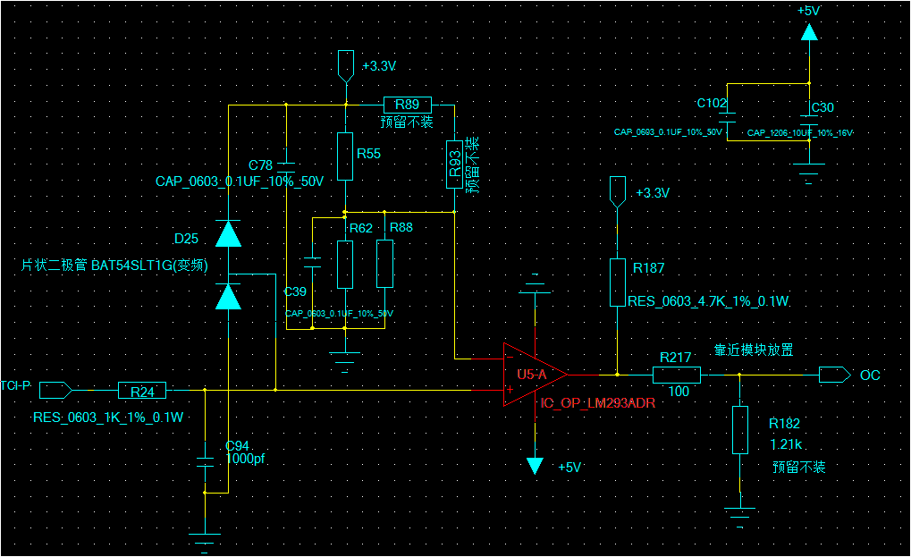
customer use LM293ADR as over current protection, but have a problem is that the set over current value is 25.9A, but when the current is only 20.4A, the LM293ADR will output high from low. the schematic as below:

  • They use 8.2mohm sense resistor for current sensing, the IN- of LM293ADR is about 0.212V. it is divide by resistor from VCC 3.3V.
  • They also test the BA10393F, it can't error trigger, the over current point is 26A which the same with set point.

first, we think it may be caused by offset voltage, but we find that the offset voltage of LM293ADR is lower than BA10393, so customer want to know which condition the output will change? does it only depends on voltage?

could you give some suggestion? thank you.

  • Hi Betty,

    What are the actual resistor values for R55, R62 and R68? Could be a difference in bias currents if they are large enough.

  • Hi Paul,

    I will ask customer to provide the resistors value. and I want to know what's the difference about the bias current? the datasheet show it maximum is -400nA.

    Here one more information is that customer used this circuit before, the sense current is lower than 16A, never found error trigger. so they also want to know if there any problem in high current application.

    if the bias current has risk, I think it should be have the same problem whatever the current is 25A or 16A, right?

    for the resistor values, I will check with customer.

    thank you

  • Hi Paul,

    R62 is 1kohm, R88 is 10kohm, R55 is 15kohm, R93 is 100kohm and R89 is 10k(25degree) NTC.

    customer removed the C94, the over current value is more lower than before. please let me know if you need more information.

  • Hello Betty,

    The resistor values are too low to be greatly affected by bias currents.

    What is the value of R24? Is it really 1k?

    Have they measured the 3.3V supply voltage also? Since this circuit uses actual voltage and is not radiometric, any changes in the supply voltage will change the threshold. The supply voltage would have to drop below 2.7V to get the trip point to change down to 20A.

    Technically, there should be no difference between the LM293A and BA10393F in this circuit. The circuit sensitivity is about 120mA per mV, so the offset voltage should cause a ±602mA variation for the BA10393, and even less for the LM293A.

    There is something else at work here...is the temperature changing?

    The currents are high enough, and shunt value low enough that layout and trace routing become critical due to IR drops.

    I would recommend using a good DMM and measuring the actual voltages directly between pins 2-4 and 3-4 to eliminate any ground drops.

    Is this a DC current? Or does it contain AC components? What is the current they are measuring.

  • Hi Paul,

    yes, the R24 is 1kohm.

    we measured the 3.3V voltage, and no found drop. the current is air-con compressor current and it measured by scope.

    the current is AC current, frequency is about 100Hz, and temperature is change from 25 degree to 60 degree.

    you said that the resistor values are too low, do you have recommend resistors values for divide resistor?

    thank you

  • Hi Betty,

    Can you get scope photos of the signals? (Preferably, +IN, -IN, OUT and V+). There is something we are missing. This circuit is too simple to fail..

    Are there negative voltages being applied to the input? Is the voltage at the +IN pin going below ground?

    By "too low", I meant that the resistor values are low enough that the few nA of bias current will not create a large error (1k * 25nA= 25uV) - no where near enough for the amount we are seeing.


  • Hi Paul,

    The IN+ and IN- signal are too small to see these because there are many noise when the compressor work. no any negative voltages applied to the input.

  • Hi Betty,

    Can they test it with a DC current? To make sure the circuit is working as designed? This will also show if there are any issues such as ground I/R drops that may be shifting the level.

    Are they using a scope or DMM to make the voltage measurements?? Scopes are not always accurate at the mV level, and DMM's will not see peaks.

    Sounds like they may be triggering on noise. The 1000pF cap may not be enough to filter. Try a 0.1uF.


  • Betty

    We have not seen any responses to this post in a little while, so we will be closing the thread.  If you need any additional assistance, please feel free to reply or open a new post.

    Thanks

    Chuck