


Other Parts Discussed in Thread: TINA-TI
Hi,
I want to connect the GND pin of TLV3501 to -5V. The VCC will be connected to 0V (thus, the voltage between VCC to GND is still +5V as specified in the datasheet).
In my understanding it should work, isn't it? Of course, all the other pins of the TLV3501 will be also referenced to the GND pin voltage: the SHDN pin will be connected to GND (-5V), and the inputs will be between 0V to -5V.
The problem is that it doesn't work in SPICE (I have tested it with Micro-cap program, I do not have the TINA-TI). Is it just a problem with your SPICE model of the TLV3501, or maybe I am wrong and my connection is illegal?
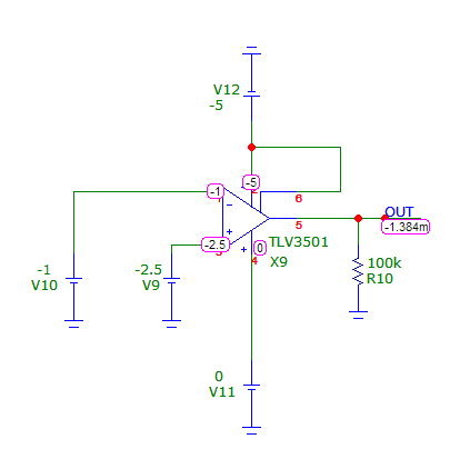
A screenshot of my SPICE results (DC operating point analysis) attached below: GND (pin2) and SHDN (pin6) are at -5V. VCC (pin4) is at 0V. The negative input is higher than the positive, so I am expecting that the output of the comparator will be at GND (which is -5V), but instead I get 0V.
Best regards,
Vadim.
