Hello everyone,
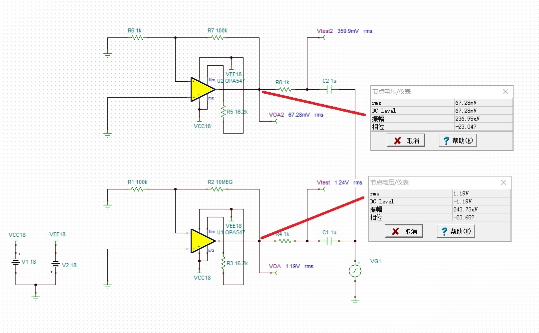
I was trying to find out the open loop output resistance Ro of opa547 with the Ro-drive method proposed by Tim Green in "Operational Amplifier Stability Part 3: Ro and Rout".
1. When doing the simulation I found there is always DC offset dominating the rms value, so the Ro-drive method did not apply. What made this happen?
2. When changing the feedback network from 1k&100k to 100k&10MEG, the AC nodal valtage change greatly. How to understand this?
3. Any suggestion to improve the simulation and help to clarify the Ro of opa547?
Regards,
Xueliang


