This thread has been locked.

If you have a related question, please click the "Ask a related question" button in the top right corner. The newly created question will be automatically linked to this question.

LM318: LM318 TINA

Part Number: LM318
Other Parts Discussed in Thread: TLV9062

Hi Sir,

We have some questions on Tina OP AMP simulation. Could you help review where we got wrong?

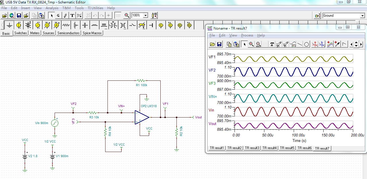
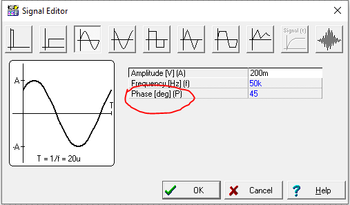
Our purpose is quite simple to amplify the OP AMP AC input voltage by 10 times.

The Tina simulation looks different what we expect. We don’t see output AC voltage 10 times of input voltage. Some questions are listed below.

  1. Is there any error in our schematic below?
  2. Tina DRC check result below: one warning: Wire is zero length or circular. What does it mean? Thanks.

USB 5V Data TX RX_0824_Tmp.TSC

  • Hi Ian,

    Looks like you're violating the input common-mode range of this device. The input common mode range for this device is between (V+ -3.5V) to (V- +3.5V). Also I notice that you're inputting an AC signal of +/- 200mV, after 10X amplification this turns out to be +/- 2V. Adding the DC offset to this you're looking at 2.9V to -1.1V. Please adjust your supply voltage to support this desired Vout. The warning sometimes shows up when a three wire joint (circular) is used for two wire connection. This may happen when actively adding and deleting wires. I've attached your circuit with TLV9062. Please let us know if you've any questions. 

    Best Regards,

    Bala Ravi

  • Hi Ravi,

     For clock and sine wave source, is there any setting for only 3 cycles output in Tina?

    And, may we set phase shift for each cycle ? For example, the first sine wave cycle is 0 degree, 2nd cycle is 45 degree and 3nd cycle is 90 degree. Thanks.

  • Hi Ian,

    Can you please provide a picture of your desired input into TINA? It is possible to change the phase by going into source settings. Please looks at the screenshot below:

    However, you can add a time delay to your circuit by adding a RC filter, where the time delay = R*C.

    Best Regards,

    Bala Ravi

  • Hi Ravi,

    Your suggestion is continuous sinewave. May we only send 3 cycles and stop?

    Or, could you suggest an external IC being able to generate sinewave?  

    Thanks, Ian.

  • Hi Ian,

    You can try the PWL function in the voltage generator. You can enter (x,y) values of Sine waves as columns (please don't add a header just values). Please find the screenshot below:


    Best Regards,

    Bala Ravi

  • Hi Ravi,

    Thanks for sharing a feasible solution. Is there a sinwave Tina sample library?

    Thanks, Ian.

  • Hi Ian,

    I don't believe there is a sinewave TINA library since we will have to physically type in the values or you can import a .txt file containing data points for a sine wave. I would recommend generating the data points in matlab and importing a .txt file to TINA by right-clicking on the white space below:

    Best Regards,

    Bala Ravi