Hello everybody!
i`am developing a high temperature preamplifier for gas analytics with the opa2333-ht
question...: can anyone tell me whats the input resistance of the amplifier? more than MOhms?
thanks a lot!!!
This thread has been locked.
If you have a related question, please click the "Ask a related question" button in the top right corner. The newly created question will be automatically linked to this question.
Hello everybody!
i`am developing a high temperature preamplifier for gas analytics with the opa2333-ht
question...: can anyone tell me whats the input resistance of the amplifier? more than MOhms?
thanks a lot!!!
Tino,
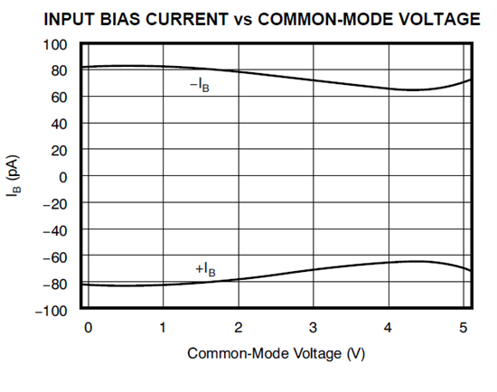
The input capacitance of OPA2333 is given in the PDS table below while input resistance may be calculated from the graph of IB vs common-mode voltage.

Considering that OPA2333 IB changes around 20pA across the 5V of common-mode input voltage (see below), this results in Rin=5V/20pA=2.5E+11; thus the input resistance is much, much higher than 1.0Mohm.

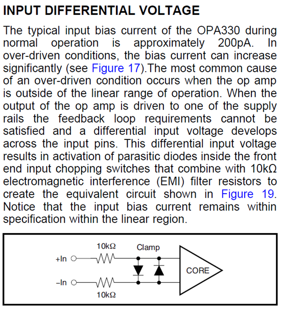
Be aware, however, that the above calculation is valid only for OPA2333 linear operation where the virtual short between the inputs is maintained through the negative feedback. If you push the output against the rail, you will cause the differential voltage to develop between the input terminals resulting in the activation of the parasitic diodes inside the OPA2333 front end (see below), resulting in IB several orders of magnitude larger than a typical value in normal operation (tens of uA instead of pA) bringing down the input resistance below 1Mohm.

here is a part of the circuit...
i had just the package of the opa2111 but its the same like the opa2333...
as you can see, it is a sample and hold circuit which has to storage the offset of the detektor periodical.
the capacity has to storage the voltage for around 0.2-0.5sec. the Riso of the cap. is around 1Gohm so tau is 100sec. the Rds of the JFET is around 10Gohm so it is not very interesting for the period of storage. but i need the Rin of the amp...
so i am ask again... 5V/5.3nA=940Mohm for Rin is that correct or is there a mistake??
thanks a lot!
Tino,
Assuming that the IB changes by 5.3nA over 5V of the input common-mode voltage at 180C, which is plausible knowing that IB typically doubles every 10C, your calculation of the Rin=5V/5.3nA=940Mohm is correct.
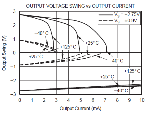
As far as the circuit diagram you attached is concern, I would just make you aware that it has the potential to loosing the virtual short between the input terminals and thus dramatically increase the IB in OPA2333 (I wrote about it in my previous answer); assuming that the 500ohm load at the output of OPA2333 is connected to Vs=5V, this may require up to -10mA output current (sinking) and that means you can only drive the output to around 0.5V from a negative rail before you saturate the output devices and thus loose the virtual short between the inputs (see diagram below). At 180C, this will occur perhaps 1V from a negative rail but I have no measured data to confirm it.

hi Marek!
thanks for your advise!
i had tested the circuit a half hour ago and i can confirm with the Rin (940Mohm) after a discharge time of around 8min--> 470sec/5 = tau =94sec-->94sec/100nF=940Mohm.
the 500ohms are connectet from Vout to Vin of a substractor and not to Vs 5V so i doent understand exactly what you mean...
thanks a lot and have a nice day!!