This thread has been locked.

If you have a related question, please click the "Ask a related question" button in the top right corner. The newly created question will be automatically linked to this question.

INA303: Draws huge current

Part Number: INA303
Other Parts Discussed in Thread: INA206

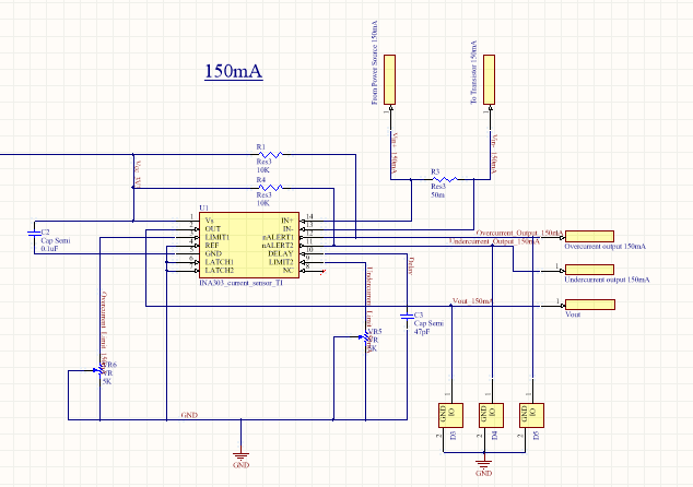
As mentioned in my earlier query, I am using INA303A2 to sense overcurrent condition set at 170mA. To test this circuit I set the load current from Power supply at 180mA and gradually increase the voltage. But the supply's short LED turns on as soon as the voltage knob is moved. This even happens even if the INA303 circuit is not powered on and only the load is powered. Any idea what could be the issue?

  • Hi Sarmad,

    Sorry to hear about the trouble.

    Sounds like it has nothing to do with INA303 though, rather it is some type of generic setup issue. You may want to double check the connections to make sure there are no unintended shorts. Then make sure the supply’s current clamp is properly set (not too small) such that it does not trip erroneously.

    If you still have trouble, please post a schematic, it is OK to show the relevant section only.

    Regards, Guang

  • Sorry couldn't share the schematic earlier. Here it is:

    Actually I have checked the connection multiple times and besides myself two of my colleagues identified the same issue at a different workbench. Surprisingly I tested this custom board earlier and it was working fine. What I would like to know is the effects of ESD on this IC. Also I would like to note that the load whose current I am monitoring is a capacitive load.

  • Hi Sarmad,

    Thanks for the schematic.

    The ESD should be invisible as long as the absolute max specifications are not violated. As an experiment - you can swap out the capacitive load with a resistive one. The in rush current is likely much higher than 150mA thereby tripping alert if you don’t have any current limiting.

    I’m also curious - Is the GND pin connected? What is the purpose of the D3 through D5 and how are they wired?

    Regards, Guang

  • Hello Sarmad,

    It's been some time since we heard from you, so hopefully your issue has been resolved. I will close the thread for now. If you need more help, please reply or post a new question.

    Best regards,

    Ian Williams
    Applications Manager
    Current Sensing

  •  

    The tripping of alert is not an issue since I have limited the current from the power supply as well. What happens is that power supply's current limit is reached as soon as the load power supply is turned on and it goes to CC mode with voltage sinking to around ~5V from 28V. If I remove this current sense circuit the load behaves perfectly fine with same power supply and current limit settings. As an experiment I sensed current drawn by this load using INA206 and it worked fine. If the problem was due to the inrush current the INA206 should have worked the same way.

    Also this current sense circuit works fine with resistive load. I have tried three different ICs of INA303 all worked fine with resistive load but when put to sense capacitive load's current they behaved abnormally.

    Yes the ground pin is connected and D3-D5 are TVS diodes not yet assembled to the PCB.

    Regards
    Sarmad

  • Hi Sarmad,

    INA206 and INA303 are obviously quite different with common mode input range being one of them.

    The excess current has to go somewhere – most likely into the INA303 input pins, with current sensing IC being the only difference between setups. If you remove the CC on the power supply, does INA303 get hot and maybe further get damaged?

    What is CC set at? Have you monitored the input common mode voltage with a scope?

    Regards, Guang

  • I couldn't get time till now to do a thorough probe, especially the parameters you mentioned. Will do and will share here as soon as I am done. But what perturbs  me is why would the inrush current find a lesser impedance path through INA303?

    CC was set at 250mA.

    Regards
    Sarmad

  • Hi Sarmad,

    250mA is a huge current to go into INA303. As part of your probe, you may want to verify and confirm. You could insert a pair of 1~10Ohm resistors on the input pins. If the current indeed is somehow going through these resistors, you should be able to measure a 0.25~2.5V voltage drop.

    Regards, Guang