This thread has been locked.

If you have a related question, please click the "Ask a related question" button in the top right corner. The newly created question will be automatically linked to this question.

OPA857: This IC doesn't work

Part Number: OPA857
Other Parts Discussed in Thread: OPA356

Hello!

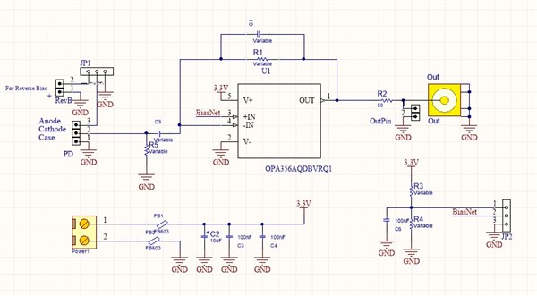
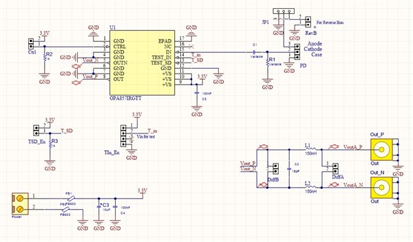
I used from OPA857 as transimpedance of photodetector at my design. It doesn't work at ac couple and I can't understand for what reasons

My photodetector is OPF430 from OSRAM and wavelength of Laser is 905 nm!

It doesn't any reaction from input at outputs! but I replaced OPA857 with OPA356 and change my design to setup this IC on transimpedance configuration. It works perfectly but I don't understand why OPA857 doesn't work! Could it be due to differential output lines?

Finally I attache both the schematic below!

  • Hi Pourya, 

    The OPA857 is design to work with a diode that is sourcing current into the amplifier (e.g. the output will move down from it's common mode). It looks to me like your configuration has the cathode of the photodiode connected to the amplifier input, which will cause current to flow out of the device (positive output). The OPA857 was designed to maximize dynamic range at the output for a negative pulse, so the output can not move positive any more than a few mV. That is likely why you are not seeing any output for your application. 

    Regards, 

  • Hi Jacob!

    Thanks for your response

    I’ll check your solution and tell you the result. But may you tell me how I can check the function of OPA857?

    I want to have a correct test scenario with details like voltage or current value, pulse or sine wave, freq and... for input and its result on the output.

    Best regards

    Pofa  

  • Hi Pofa, 

    If you have the OPA857 EVM, you can use the test mode configuration to understand the function. In order to test the part correctly with your schematic, you would have to set the diode up to source current into the part. This should be possible by connecting the anode to the input of the amplifier and providing a few volts of reverse bias. 

    Regards, 

  • Hello Pofa,

    Were you able to properly test your design?

    Best,

    Hasan Babiker

  • Hello,

    I am closing this thread due to inactivity. Please reply or start a new post if further discussion is needed.

    Best,

    Hasan Babiker