This thread has been locked.

If you have a related question, please click the "Ask a related question" button in the top right corner. The newly created question will be automatically linked to this question.

TL072A: output coming in groups of 16 points

Part Number: TL072A
Other Parts Discussed in Thread: TL072, , TLV9002

Hey, everyone!

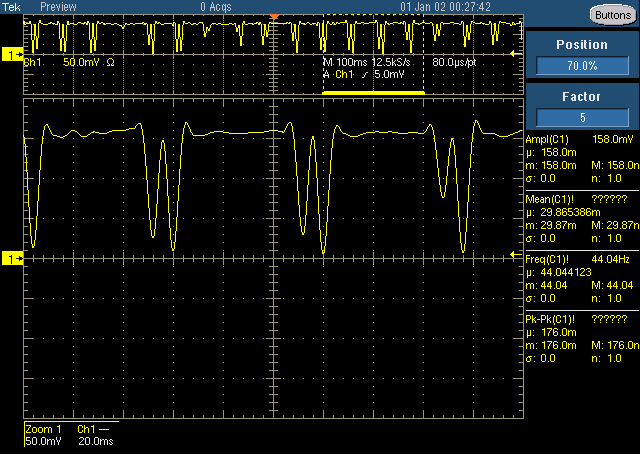
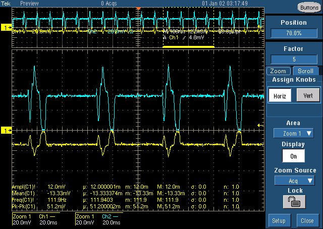
I am using TI Hercules RM57Lx LaunchPad to signals from a photodiode. The photodiode gives a negative voltage, so, I am using TL072 IC for getting an amplified inverted signal. I connect to output from the TL072 IC to AD0 ( which is the input for ADC) on the RM57Lx microcontroller board.

When the data is collected and plotted, it is seen that they are not really continuous but in groups of 16 points. I am also attaching a cropped image of the plot for reference.

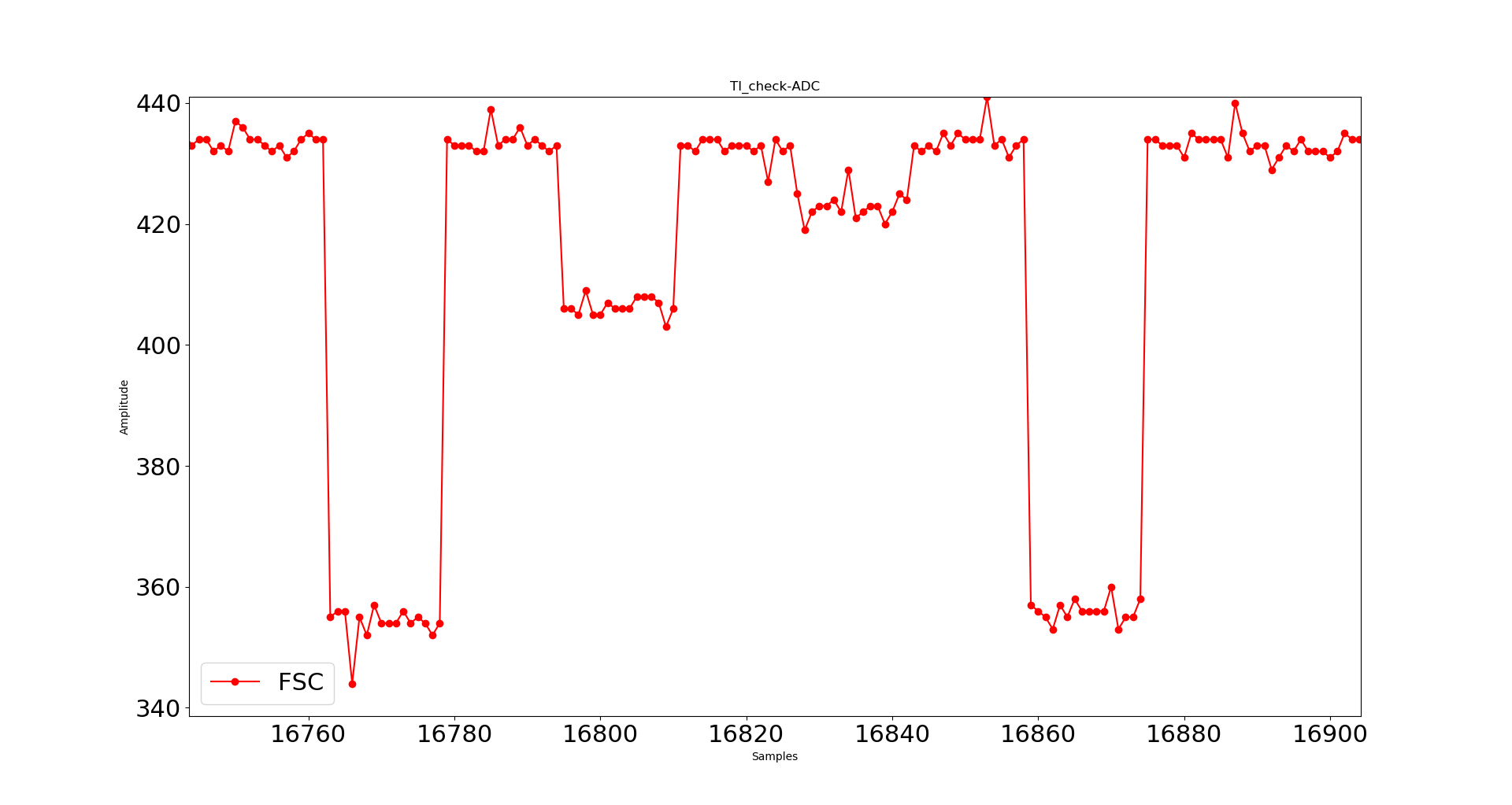
Please, tell me what is the issue and how to resolve that.

Thanks and regards,
Apurv

  • Hi Apurv,

    What is the input to TL072A? Can you also provide a waveform of the output before going to the ADC?

    Best Regards,

    Bala Ravi

  • Hi, Bala!

    The input to TL072A is from the photodiode, would be around 15mV.

    Below is the waveform of the output before it goes to the ADC:

    Thank you.

    Regards,
    Apurv

  • Hi Apurv,

    What is your supply voltage to TL072A (Vcc and Vee)? Is input a DC voltage of 15mV or a sine wave? 

    Also please be aware that the typical offset voltage for this device is 3mV with a max rating of up to 13mV. This is something to keep in mind since you're inputting a small voltage. If you would like an alternate device please check out TLV9002 which has a max offset voltage of 2mV. 

    Best Regards,

    Bala Ravi

  • Hi!

    The supply voltage is +4.5V and -4.5 by using voltage divider like circuit of two 9V batteries.

    Yes, the input is a DC voltage from photodiode, the dips in the graph are when light falls on the photodiode.

    Yours,
    Apurv

  • Hi Apurv,

    Can you please share your schematic? I would like to look at your inverting-amplifier circuit. Also can you please provide the output of photodiode and output of TL072A in the same screenshot?

    Thanks,

    Bala Ravi

  • Hey, I do not have a drawn schematic but the following is the screenshot that you asked for.

    The blue one is the output from TL072 and the yellow one is from the photodiode.

    I think the inverting circuit is working fine. I have kept a gain of 2.5.

    But, still, the ADC output from RM57Lx is not accurate. The ADC output is below (not exactly corresponding to the above figure as taken at different times):

    Why are the points grouped in 16 points?

    Thank you for your time.

    Regards,
    Apurv

  • Hi Apurv,

    Yes, seems like the inverting amplifier circuit is working fine. I'm not completely sure about the ADC output, but I will move this thread to an ADC expert and they will be able to better assist you. 

    Best Regards,

    Bala Ravi