This thread has been locked.

If you have a related question, please click the "Ask a related question" button in the top right corner. The newly created question will be automatically linked to this question.

XTR111 Question

Other Parts Discussed in Thread: XTR111, DAC7551

My customer asks:

I plan on using 2 XTR111 and I would like to know if I can tie the 2 regulator out pins together so I can assure that I can supply enough current to the VDD2 side of my digital isolator. At worst case I would need 5.3mA and the XTR111 can supply up to 5mA so I know I wouldn’t get 10mA by tieing the 2 together but all I need is another 0.5mA.

  • Rob,

    First, there are REGF (force) and REGS (sense) pins to each XTR111 regulator which you are typically supposed to tie together close to the load in order to minimize the effect of varying loads on the regulation output voltage - thus you need to deal in your question with four pins and not just two (see upper left section of the simplified XTR111 below).


    You may NOT simply tied them together because each regulation voltage in XTR111 may vary by as much as +/-150mV (see table below) and connecting them together would force them into short circuit condition.  Therefore, you need to use balancing resistors in order to be able to add the two output currents.


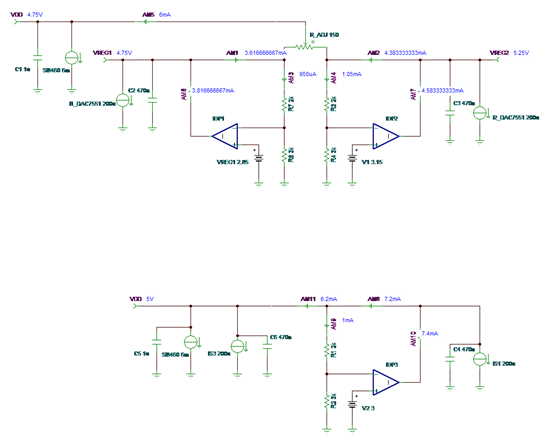
    One way to do that is shown in the simplified schematic below.  Since the worst differential voltage between the two regulator may be as high as 300mV, in order to assure that NONE of the regulators will be required to deliver more than 5mA of current out of the of total maximum required of 5.3mA, you need to use 64ohm or higher balancing resistors.


    Having said that, knowing that the regulator typical short circuit current is 21mA (see table above), you can most likely get away with a single regulator providing entire 5.3mA worst case current.

  • So just to be clear the customer would use a schematic similar to the one in Figure 46 of the XTR111 datasheet except I would have that twice and use 64 Ohm series resistors after each to power the digital isolator?

     3718.Doc2.pdf

  • Rob,

    The way you configure your circuit in your attached schematic requires an extra 2mA current to bias gain resistors.  Actually, you will need even more IQ current because you have to use max IQ for DAC7551 of 200uA and not a typical value (see table below).


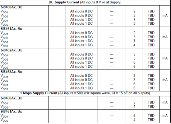
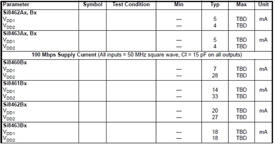
    I do not know what configuration and data rate you use in SI8460 but make sure you choose the correct max IQ value for VDD's since they vary anywhere from 2mA to 33mA (see table below). But even the lowest IQ values shown are just a typical specs thus you need to  increase them at least by 20% to 6mA for the max value.


    Make sue you place 1uF bypass capacitor right at the VDD1 and VDD2 pins (see below).


    You may use an adjustable resistor to balance the loads - see below.

    Are you combining the VDD1 and VDD2 DC Supply Currents of SI8460 to arrive at the total required 5mA?  If so, you should simply use one XTR111 regulator output to bias individually each VDD of SI8460. 

    You should seriously consider using just a single XTR111 regulator in your application (see above) since the precision of regulator voltage is not critical in powering SI8460 and its maximum output current (short-circuit current) is 21mA (see below).