This thread has been locked.

If you have a related question, please click the "Ask a related question" button in the top right corner. The newly created question will be automatically linked to this question.

OPA2317: replace instead of LMC6082IMX

Part Number: OPA2317
Other Parts Discussed in Thread: ADS124S08, OPA317, LMC6082, INA326, INA333

Hi,

When we LMC6082IMX opamp for 24 bit ADC application. found that the LMC6082IMX offset voltage is more. So found low offset voltage opamp OPA2317 to replace the LMC6082IMX.

considering offset voltage the OPA2317 is excellent; apart from offset voltage any other critical parameter need to check ?? 

OP2317 will work for my circuit ?? 

  • Hi Arumugam,

    Yes, the OPAx317 amplifiers offer very low offset and near zero offset drift without flicker noise due to the internal offset auto-calibration correction. Since your RTD signal of interest is very low frequency, and the ADS124S08 has relative high input impedance, the difference in bandwidth between the LM6082 and OPA2317 is not a concern.

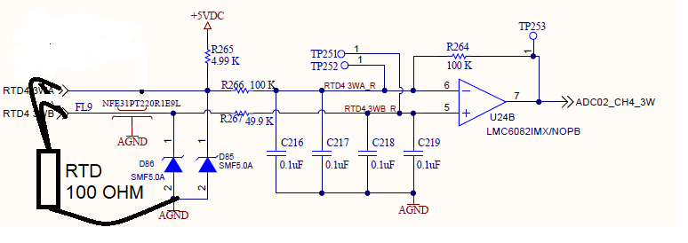
    On the partial schematic above, shows the RTD4_3WA net connected to +5VDC through a 4.99k resistor. How is the RTD4 3WB connection biased? If the complete schematic is available, showing the RTD connections, we will be happy to review.

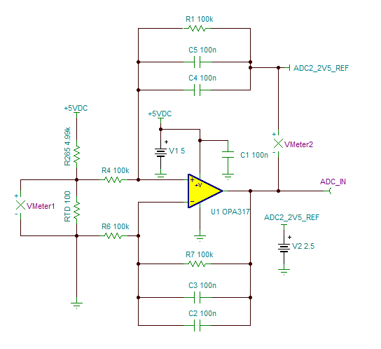
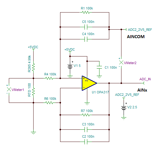
    Depending on how the RTD is biased, if you intend to measure the differential signal across the RTD and perform a differential to single-ended conversion using the OPA317 to feed into the ADC, a possible option is to configure the OPA317 on a difference amplifier configuration (instead of the inverting configuration). Please see one possible circuit below.

    Thank you,

    Kind Regards,

    Luis

  • Hi Luis,

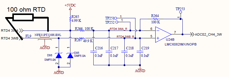
    Thanks for your reply. Find the below snap on the RTD connection in amplifier circuit. Since Layout and PCB was manufactured; i am not interested to change the circuit .

    I interest to change only the low offset opamp OPx317 instead of LMC6082.

    Just want to make sure any additional error will not add due to OPx317 part. Please confirm the circuit is work with OPx317 part ??

    Thanks and Regards,

    Arumugam.P

  • Hi Arumugam,

    The OPA317 or LMC6082 should work in the RTD measurement application; however, I have questions about the amplifier used in the inverting configuration and the RTD connections.

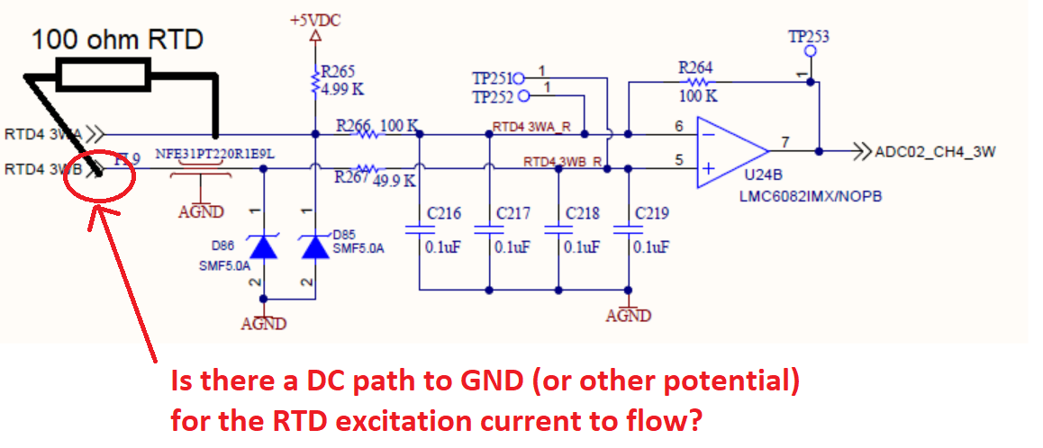
    1)      The schematic does not clearly show a DC path connection of the RTD negative side (RTD4 3WB), Is this side of the RTD connected to GND? The diagram shows a connection through an EMI filter (NFE31PT220), connected to cathode TVS diode (SMF5.0A) and then through R267 resistor to the amplifier input positive terminal (Op-amp high impedance input). Is the RTD Grounded or connected to a DC potential for the RTD current to flow? Please see below and clarify if I misunderstood the schematic.

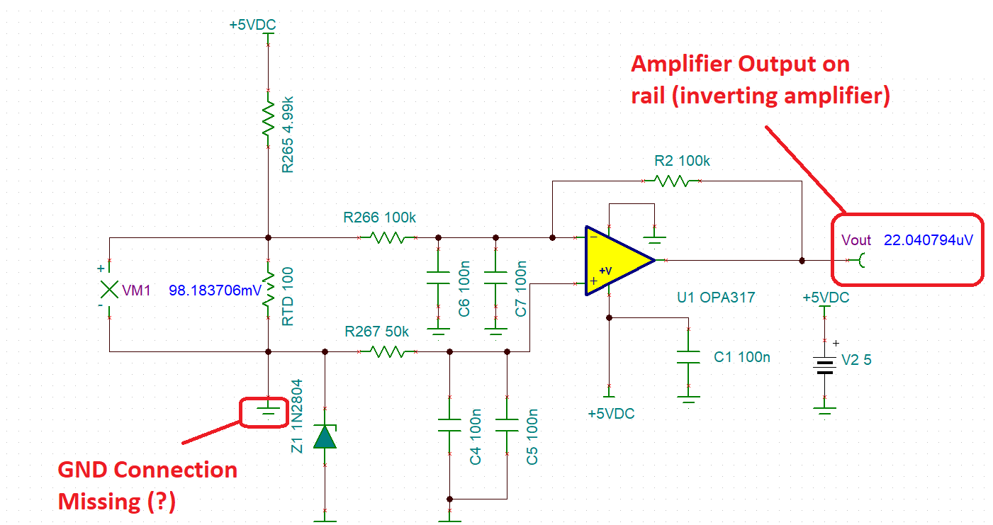
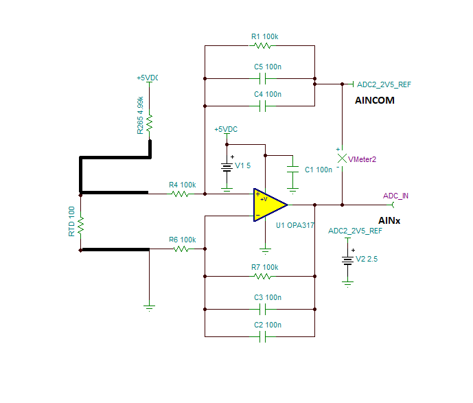
    2)      The OP-AMP is in the inverting configuration. If we assume that the negative side of the RTD is grounded, the RTD will produce a positive signal in the range ~100s of millivolts range (assuming PT100) above GND. The OPA317 will attempt to invert this signal, and produce a negative voltage placing the amplifier in the negative rail, outside of linear range of amplifier. Also, since the ADS124S08 is powered with a +5V DC uni-polar supply, the signal must be within the valid voltage range of the ADC. Please see image below, with amplifier outside of linear range and outside of ADC voltage range. Kindly clarify if the RTD is biased to a different DC voltage that allows using the inverting configuration.

    In the circuit below, the amplifier output is shifted to the proper DC bias inside the range of the ADC. The difference amplifier output is referred to 2.5V (ADC AINCOM). The ADS124S08 can be configured to perform conversions in single–ended configuration, with ADC converting the difference between AINCOM and AINx.  

    Thank you and Regards,

    Luis

  • Dear Luis,

    Thanks for your answer.

    I apologizes missing GND connection for RTD connector. I have modified and uploaded the corrected circuit.

    RTD bias through the 4.99K / 0.01% with +5VDC (current limit to ~ 1mA).

    ADC configured single ended configuration, Internal reference for measurement

    ads124s08-2" 1 0x02 0x0C  -  This sets the measurement to channel 1 and AINCOM.

    ads124s08-2" 1 0x04 0x3C  -  This sets the measurement to single shot, low latency, and 2000 samples per second.

    ads124s08-2" 1 0x05 0x11   -  This sets the Internal Ref to on and enables the external reference for measurements.

    Please help my existing circuit will work with OPAX317 with low output offset. 

    Also please help and suggest if any modification required in the circuit and ADC configuration ?

    Thanks and Regards,

    Arumugam.P

  • Hi Arumugam,

    Unfortunately, the circuit on your last post will not work. The RTD needs to be wired to measure the voltage difference across the RTD, and in the circuit posted above, the amplifier has shorted both inputs of the amplifier. The OPA2317 needs to be configured as a difference amplifier configuration to measure the differential signal across the RTD and to shift the signal to the common-mode voltage level of the ADS124S08. A possible circuit using a difference amplifier with is below. Please note, this circuit uses an excitation voltage, and the RTD sensor wire resistances will cause voltage drops, causing errors in the RTD measurement. If you are not concerned with the induced errors of the RTD sensor cables in the measurement, you could use the circuit below with the OPA2317 in the difference amplifier configuration (instead of inverting), with the RTD connected to GND; and the difference amplifier referred to ADS124S08 AINCOM.

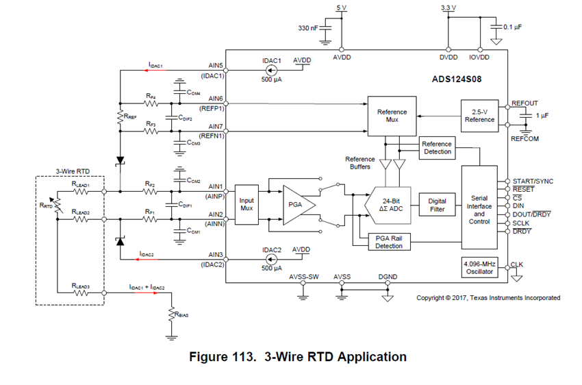
    However, in most cases, high precision 3-wire RTD applications use two excitation current sources (instead of a voltage excitation) and connect the three-wire RTD sensor as shown the image below.  Since 3-wire RTD sensors have matched wire resistances on the terminals, by using two well-matched current sources, the voltage drop errors due to the wire resistances of the RTD cables tend to cancel, allowing an accurate measurement of the RTD.  The ADS124S08 incorporate two well matched RTD current excitation sources and it is designed to measure the RTDs differentially. One possible circuit configuration for 3-wire RTD with the ADS124S08 is shown below.  The ADS124S08 also incorporates a high impedance PGA that allows you to connect the RTD differentially directly into two inputs of the ADS124S08 without an external amplifier.


    For reference, The application note below discusses 2-wire, 3-wire and 4-wire RTD connections in great detail:

    http://www.ti.com/lit/an/sbaa275/sbaa275.pdf

    If you are looking into converting the RTD differential into a single-ended signal in order to use less channels of the ADC (performing single-ended measurement), and are concerned about eliminating the RTD wire resistance errors, you may consider an instrumentation amplifier design as featured on the application note below. The circuit below also shows how to use two matched excitation currents; eliminating the errors due to the RTD wire resistance connections, and allowing a higher precision measurement. You could replace the INA326 in the design with the INA333, connecting the VREF input of the INA333 to 2.5V (VCOM of ADS124S08) and adjusting the gain resistor for the INA333.  Let me know if you have questions about this circuit.  Please see application note below.

    http://www.ti.com/lit/ug/tidu969/tidu969.pdf

    Thank you and Regards,

    Luis