This thread has been locked.

If you have a related question, please click the "Ask a related question" button in the top right corner. The newly created question will be automatically linked to this question.

RCV420: RCV240 : 0-5 v range and 2 wire mounting with ISO124

Part Number: RCV420
Other Parts Discussed in Thread: ISO124, , XTR105, OPA602

Hello everyone,


I want to use a RCV420 with a 0-5v output range and isolated by an ISO124.
with the help Luis Chioye, I followed the example of the application bulletin of BB, (SBVA004).


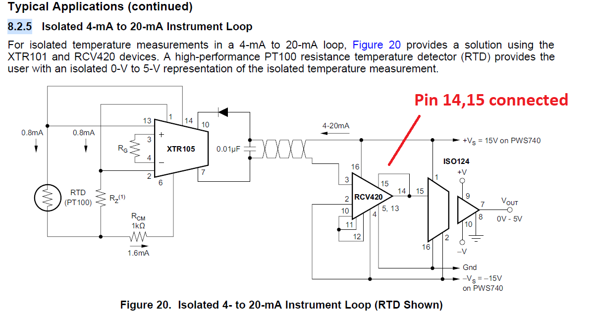
But when I make the example of 2-wire mounting of the isolator ISO124, (SBOS074A, 8.2.5).
there is a lot of modification on RCV420 connections.
- We lose the common pin 2 for measuring range reduction resistances, for example.

-As I will use several RCV420, the fact that they are connected by the gnd before ISO124 disturbs me.

for me, the insulation is no longer perfect.
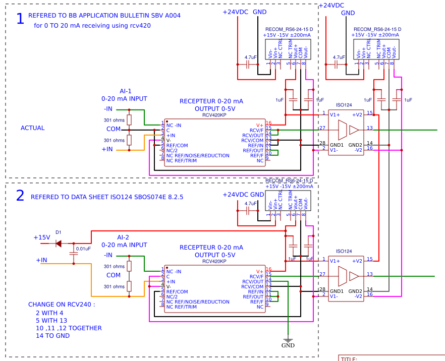
attached, an image of the two montages,

can someone explain to me?
is there another way to have a 2-wire mount keeping insulations between the RCV420?
and is the + 15v sufficient to power the 4-20 mA sensor?

Thanks for your help.
richard

  • Hi Richard,

    There is a difference on the transfer function, CIRCUIT (1) produces a 1-V output for 4mA input, while the circuit SBOS074C, 8.2.5, produces a 0-V output at 4mA input.

    CIRCUIT 1: 0-20mA input, 0V-5V output (or equivalently 4-20mA input, 1V-5V output)

    On out previous post: https://e2e.ti.com/support/amplifiers/f/14/t/840274, we discussed a circuit per your request, that accepts a 4mA to 20mA input and generates a 1-V to 5-V output.  This CIRCUIT (1) on your post above is correct, uses external 301-ohm resistors, CT is connected to GND, REFIN (pin12) is connected to GND.  This same circuit will work accepting a 0mA-20mA input to generate a 0 to 5-V output.  The current loop supply GND is the same as the RCV420 ground.

    CIRCUIT 2: 4-20mA input, 0V-5V output (notice key difference at 4mA input, 0-V output)

    The circuit below, (SBOS074E, 8.2.5), accepts a 4mA to 20mA input, and generates a 0-V to 5-V output.  Please note, per circuit 8.2.5 of the latest revision of the datasheet on page 16, pin15 Rcv fb and pin 14 Rcv out must be connected together (please correct on your schematic Circuit 2 above).  Also, as you have mentioned, for this circuit the external 301 resistors are not required, CT (pin 2) connects to Pin4 (V-), REFIN (pin 12) connects to REFOUT Pin 10 and pin 11.  Please see figure below. 

    Regarding your sensor supply requirements, if you are using the XTR105, using a 15-V supply is sufficient... If another device/circuit is used on your sensor application, you will need to look at your sensor compliance and supply requirements.

    Let me know if you have additional questions.

    Thank you and Regards,

    Luis 


  • HI Luis,
    I am confused, I made several big mistake, to do the drawing I mixed the pins of pin of RCV420 and ISO124,
    and what's more, I used ISO124 DIP pin markers for ISO124 SOIC pin markers.
    and in the data sheet, I understood the sign "-" for "to" not for "negative".
    dumb ....

    in the application bulletin SBVA004, I just saw that it must be the pin 1 connected in the loop to have: input current 0 to 20 mA, output voltage 0 to 5v.
    could you confirm that, please, I'm getting lost ...

    * also, I kept drawing 1: because I want to keep the measuring range of the circuit 1: 0 to 5v for 0 to 20 mA input.

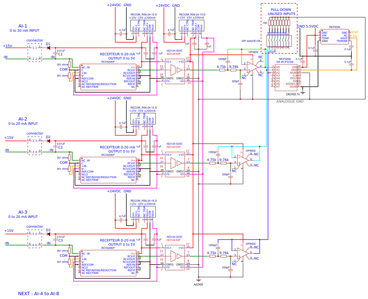
    - would the modified drawing 1 be good for a 2-wire system,
    with input current 0 to 20 mA = 0 to 5v at the output of OPA602?
    - what should be the characteristics of D1 and C1?
    I do not find that in the data sheet

    * not all measurement channels will necessarily be used,
    but I want to physically keep the measurement channels.
    - are the pull-down resistor required at the output of OPA602 for unused MCP3008 inputs?
    - or does OPA602 maintain a potential at 0v if there is 0 mA at the input of RCV420?

    the sensors I want to connect have power ranges of 9 to 30 vdc or 12 to 36 vdc, so 15 vdc will be suitable.


    below the drawing 1 modified


    Thank you.

    Richard

  • Hi Richard,

    Sorry for the delayed response.

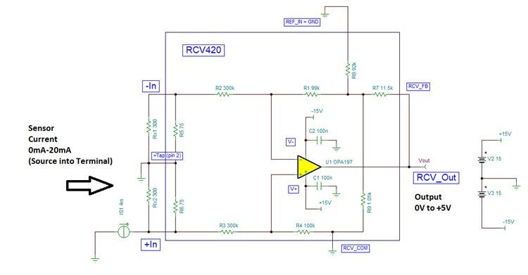
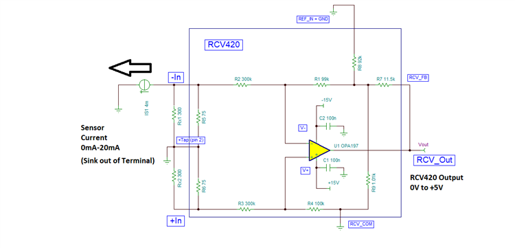
    If the sensor sources the 0-20mA current into the input terminal, as shown below with the current flowing into RCV420 the terminal in the diagram below, the user needs to connect the sensor into the +IN terminal of the RCV420 as shown on the diagram below to produce a 0V to +5V positive voltage output.

    If the sensor sinks the 0-20mA current out of the input terminal, as shown below with the current flowing out of the RCV420 terminal in the diagram below, the user needs to connect the sensor into the -IN terminal of the RCV420 as shown on the diagram below to produce a 0V to +5V positive voltage output.

    On your drawing 1, if your sensor sources the current into the terminal, you will need to connect the sensor to the IN+ terminal to produce 0-5V output for a 0-20mA input current. 

    Please check the recommendations with the MCP3208 manufacturer on unused input pins (non TI device).  In most cases is safe to use a pull-down resistor on unused ADC pins.

    The RCV420 will drive the output to 0-V if no current is present, therefore the amplifier will drive the ADC to 0-V for no current present.

    Thank you and Best Regards,

    Luis