This thread has been locked.

If you have a related question, please click the "Ask a related question" button in the top right corner. The newly created question will be automatically linked to this question.

PGA281: Below 10nA current measurement range?

Part Number: PGA281
Other Parts Discussed in Thread: OPA2191, OPA2197

With the PGA281 is it possible to measure 10uA to 100mA with a voltage of ±15V.

We use it as a High-Side current measurement solution.

My question is:

1. Is it possible to measure 10nA with an input voltage of ±15V. If Yes How??

If No

2. Is there an other PGAxxx or something else with a programmable gain that does lower currents at high voltage range (±15V. )

  • HI Steven,

    You may already have seen the TI Reference design using the PGA281 to measure 10-uA to 100mA current.  The design uses a 6.8-ohm resistor to measure the 10-uA to 100mA current.  The maximum voltage drop across the shunt is ~680mV.  The % error of full-scale is ~0.05%.  The relative error at 100mA is 0.01% and the relative error at 10uA is 33%. If you are required to measure  high sense shunt resistor with a voltage of 15V, you will need to power the VSP supply of the PGA281 with a voltage above 15.5V.

    Please see link for the TI reference Design, 10uA-100 mA, 0.05% Error, High-Side Current Sensing:

    http://www.ti.com/lit/ug/tidu033/tidu033.pdf

    Regarding the question of measuring a 10nA current, the input bias current of the PGA281 is in the order of ~2nA, therefore, the input bias current of the PGA281 will create unacceptable large errors.  A possible option is to buffer each input of the PGA281 with a high voltage, rail-to-rail, precision CMOS input amplifier such as the OPA2191.  CMOS amplifiers have a much lower bias current in the range of +/-5pA.   The second issue is that the 10nA current is much smaller than 10uA, and the shunt resistor will need to be scaled to be able to measure the small 10-nA current.   If you need to incorporate a solution that encompass the complete range from 10nA to 100mA on the same solution, this is challenging since you are trying to measure current ranges across 7-order of magnitude, and this will probably require to implement a solution with selectable shunt resistors depending on the current range.

    We have low input bias current, 36-V FET input instrumentation amplifiers that will be optimal to measure the 10nA current on a high side shunt resistors at 15-V; but, unfortunately, these devices do not offer programmable gain.

    Thank you,

    Luis 


  • Hi Luis

    Thanks for you're answer.

    The PGA281 Reference design I have tested indeed. That's way I wanted such a solution but then for lower currents range.

    You are talking about low input bias current, 36-V FET input instrumentation amplifiers, this can be a good solution.

    I can use this maybe for 10nA to 10uA and the PGA281 for the 10uA to 100mA.

    Can you tell me which TI component range I need to check that also have reference designs.

    Best regards

    Steven

  • Hi Steven,

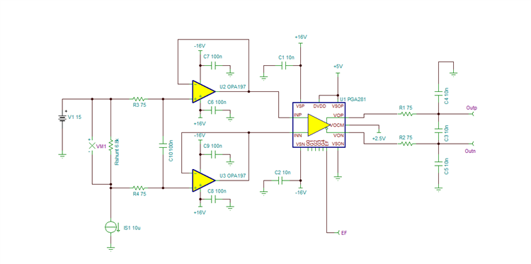
    If you require the programmable gain, measuring the 10nA to 10uA shunt current, one possible option is to buffer both INP and INN PGA281 inputs with the dual OPA2197 configured in the follower configuration. 

    A possible circuit is below using the PGA281 and OPA2197. The circuit is essentially the same as the original PGA281 reference design, where the shunt resistor has been adjusted to 6.8kOhm to accommodate a 10nA to 10uA current range, and the PGA281 inputs are buffered with the OPA2197.  The OPA2197 is a dual, CMOS (low input bias current), precision, 36-V, rail-to-rail input output, low offset op amp.

    Thank you,

    Best Regards,

    Luis Chioye


  • Hi Luis

    Sorry for the late reaction.

    I ordered the OPA2197 and build it up like the schematic is shown. I increased the 16V to 17V and decreased the 5V and 2.5V to 3V3 and 1.65V.

    I need to be aware that the output of the buffers are <15.5V otherwise the input of the PGA will be to high.

    In this case the EF LED stays off and I can measure indeed lower currents (<1uA).

    So far so good for my solution. I will keep you posted.