This thread has been locked.

If you have a related question, please click the "Ask a related question" button in the top right corner. The newly created question will be automatically linked to this question.

TLV9002: Integrator circuit's DC operating point

Part Number: TLV9002
Other Parts Discussed in Thread: UA741

Dear team

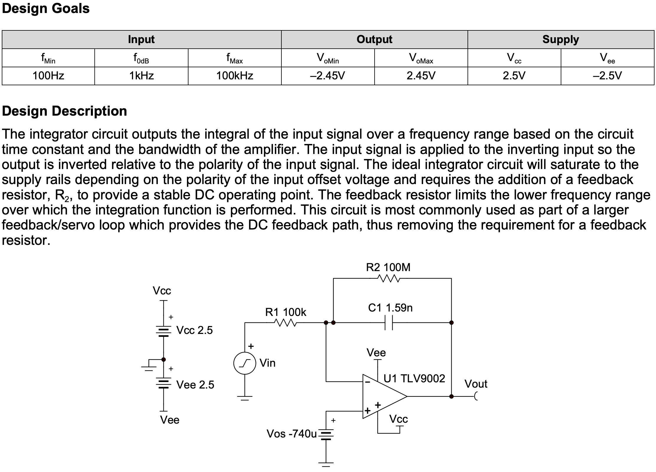
May I ask about the sboa275a? http://www.ti.com/lit/an/sboa275a/sboa275a.pdf

Instead of using TLV9002, I used UA741 for the experiment.

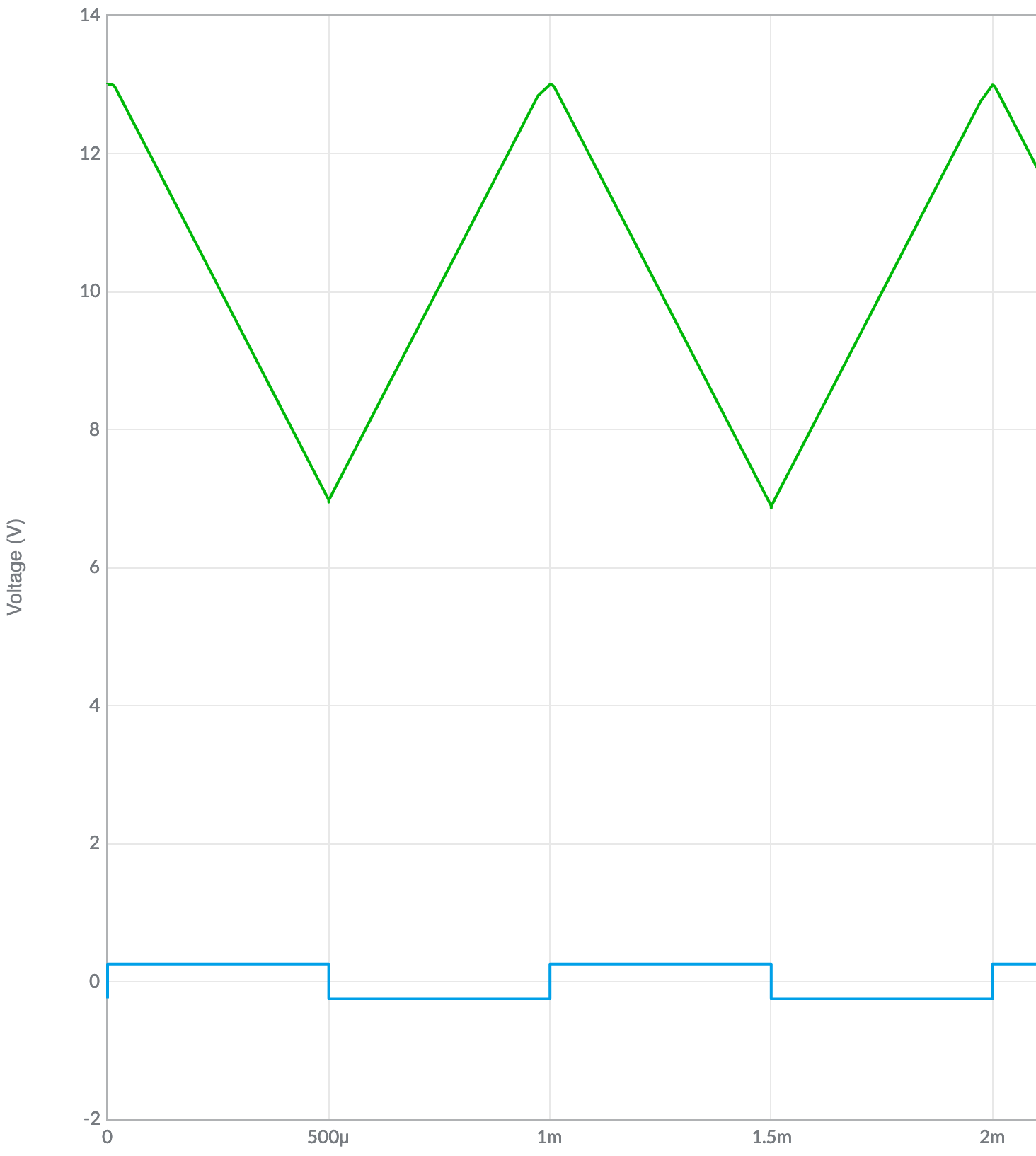
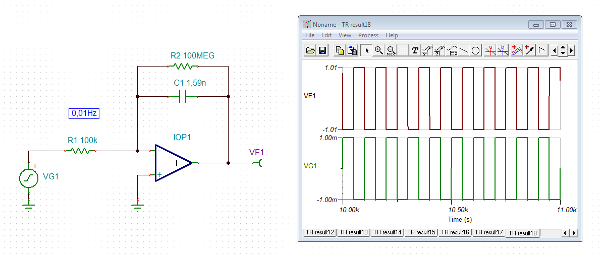
When supplying +15/-15V power and 1kHz square wave, the output looks like a triangle.

If the R2 is removed, the triangular output stays near to the 15V power supply voltages.

May I ask

Q0. "The ideal integrator circuit will saturate to the supply rails depending on the polarity of the input offset voltage"

Is this the case; ideal integrator meaning no R2 resistor? Then without R2, why this becomes saturated?

Q1. "requires the addition of a feedback resistor, R2, to provide a stable DC operating point."

May I ask the meaning of this "stable DC operating point"?

Q2. "The feedback resistor limits the lower frequency range over which the integration function is performed."

Why does the feedback resistor limit only the lower frequency range?

Thanks for the help.

  • Hi David,

    Q0 - Yes, this is referring to an integrator circuit without R2. The reason it saturates is because there is no DC feedback. However, an integrator is often uses inside of another feedback path that provides DC feedback.

    Q1 - Without the resistor R2 there is not a DC feedback path because the feedback capacitor is an open at DC and is therefore an open loop circuit at DC.

    Q2 - The feedback resistor and feedback capacitor form a pole and limits the frequency range. This is similar to an inverting amplifier with a feedback capacitor to limit the bandwidth.

    Thank you,

    Tim Claycomb

  • Thanks for your kind answer, Tim.

    Before closing this, I wish to double-check; about the "DC operating point"

    if the Op Amp's circuit cannot become a closed-loop circuit when using a DC input (in this case, the capacitor acts as an open circuit for DC input),

    this circuit cannot provide a DC feedback path and there is no DC operating point, right?

  • Hi David,

    to your question Q2:

    At frequencies much higher than 1 / (2 x pi x R2 x C1) = 1Hz the parallel circuit of R2 and C1 looks like a capacitor (C1). Because the impedance of C1 is much smaller than R2 for these frequencies, all the current flows into C1 and not R2. So, at frequencies much higher than 1 / (2 x pi x R2 x C1) = 1Hz the circuit works as an integrator.

    At frequencies much lower than 1 / (2 x pi x R2 x C1) = 1Hz, on the other hand, the parallel circuit of R2 and C1 looks like a resistor (R2). Because the impedance of C1 is much bigger than R2 for these frequencies, all the current flows into R2 and not C1. So, at frequencies much lower than 1 / (2 x pi x R2 x C1) = 1Hz the circuit no longer works as an integrator but as an inverting amplifier with the gain -R2 / R1.

    At frequencies arround 1 / (2 x pi x R2 x C1) = 1Hz the circuit behaves as a mix of both, integrator and inverting amplifier.

    R2 is often omitted when the integrator is part of a DC servo. Then, the DC feedback is provided by the overall feedback. Also read this very interesting article written by the awesome Rod Elliott:

    Kai

  • Hi Kai,

    Thank you for providing such a helpful response to David's questions.

    Thanks,

    Tim Claycomb