This thread has been locked.

If you have a related question, please click the "Ask a related question" button in the top right corner. The newly created question will be automatically linked to this question.

OPA2376: cross talk

Part Number: OPA2376

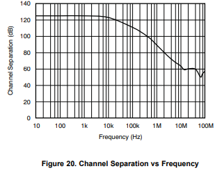
Is there a graph for the cross talk versus frequency in the OPA2376 dual op amp?

I am assuming that it gets worse with increasing frequency.

I have a 15kHz sine wave coming out of pin 7 at 2Vpp.

I have a 3mVpp 15kHz sine wave coming out of pin 1.

I am certain that this unwanted event is happening inside the chip.

Both op amps are inverting with a gain of 0.1(yes they attenuate the signal). 

The power supplies are +-2.5V.

I am thinking that an opamp with a wider bandwidth may improve things.

Regards

Tim Orr

  • The graph of the OPA2376 cross talk (channel separation) is shown in Fig 20 - see below.  At f=15kHz it shows around 120dB with RL=10kohm load, which would mean you should see 2uVpp at pin 1 with 2Vpp at pin 7 assuming that the input of channel 1 is grounded (it cannot float) and the input and output voltage are within the OPA2376 linear range.  However, if the load on pin 7 is heavier than 10kohm specified in the datasheet (e.g. RL<1kohm), this would result in a lower channel separation.

    Also, a signal bandwidth has little to do with the channel separation.  Thus, you should NOT expect channel separation to be necessarly higher in parts with higher bandwidth.

  • Hi Tim,

    We haven't heard from you in a while. We hope the issue was resolved. I am going to close this thread now. If you have any additional comments, please reply to re-open.

    -Tamara

  • Hello Marek,

    Many thanks for your comments.

    I also saw the graph in the data sheet. In my experience you never get 120dBs of separation. There was no test set up so it was difficult to understand how the results were obtained. In particular, a 5.5MHz opamp was tested to 100MHz. I thought that perhaps it was a graph for another part! The top 94.5MHz of the graph is beyond the unity gain of the op amp.

    Both parts of the inverting virtual earth circuit had a 10k feedback resistor and a 100k input resistor. The outputs went to a stereo audio ADC via a 100R resistor and a 470nF capacitor.

    All investigations suggested the signal in pins 6,7 (2Vpp) appeared as a 3mVpp at pin 1 via the op amp.  This is a 300nApp current into a 10k resistor. I disproved cross talk in the signal tracking (a 6 layer PCB).

    Today,s world of digital scopes makes it impossible to see small signals. One company I worked with keeps an old analogue scope so that they can see these small signals.

    In the end I used my 60dB low noise battery powered small signal amplifier with low pass filtering. A 1mV noisey signal appears as a 'clean' 1V signal on the scope. This allowed me to see the 3mV crosstalk.

    The circuit is trivial. One op amp and two resistors. I decided to lower the impedance levels in the 'victim' section to 1k feedback and 10k input. The crosstalk sank into the noise floor. I do not know why. I expect that it is still there but just smaller by a factor of 10.

    Best regards,

    Tim Orr