This thread has been locked.

If you have a related question, please click the "Ask a related question" button in the top right corner. The newly created question will be automatically linked to this question.

LM358: P

Part Number: LM358
Other Parts Discussed in Thread: TINA-TI

Hello 

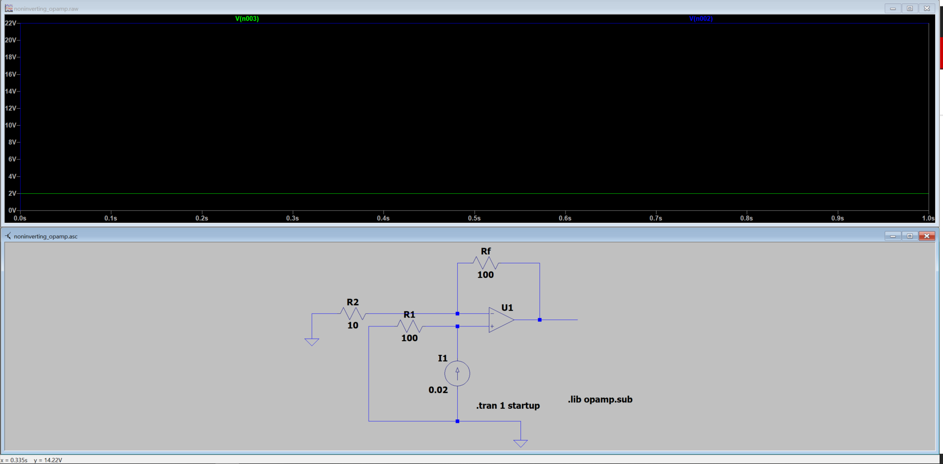
I'm trying to implement a simple non-inverting amplifier. The input voltage to the non-inverting pin (3) is 2V. Rin and RF are 10 and 100 ohms. This would mean the gain should be 11. Then the Vout should be 22V. At least that's what LT spice simulation says. However, that's not the case for some reason. No matter the input, I'm getting 3.7V at the OUT1 (PIN 1).  

Then I tried to implement an inverting amplifier exactly the way the datasheet of LM358 (Section 10.2.2) suggested. I still didn't get the expected output. The input voltage was 2V while Rin and RF were 320 and 1000 ohm. So the Gain in this scenario is 3.125. So we should get an output voltage of around 6.2V. But I'm getting an output of 0.6V at PIN 1. 

Any thoughts?

Note: Opamp is power by 12V (PIN 8) and PIN 4 is connected to 12V ground (0V). (NOT -12V). I hope this is not the reason why it's not working. 

  • Former Member
    0 Former Member

    Hello,

    Thanks for your question and welcome to the forum!  I'll break down my answer into your two cases.

    Before we begin, I'd like to point you to our TINA-TI software.  This is a free software that we typically use for schematics and circuit simulation.  TI makes TINA models for all its parts, making TINA very convenient.  TINA is also convenient because it is very easy to share circuits.  I've recreated one of your circuits here and will include it below.  You will see that just by having TINA-TI, you will immediately be able to open the file and run any tests I set up.  No messing around with libraries.

    As for your questions:

    1.  For the first circuit, you are experiencing issues because you are trying to get the output of the amplifier to go past the positive rail.  One of the rules of op amps is that they cannot output a voltage higher than their positive supply or lower than their negative supply.  Consequently, you will not get the desired 22V at the output of the amplifier.

    2.  For your second circuit, you are not obtaining your desired output because the inputs are biased right at your negative rail, which is 0V.  The inputs of the amplifier need a little bit of headroom away from the rails to be able to operate in their desired, linear operating region.  You will see that if you change your negative rail from 0V to -12V, then your circuit will work as expected!

    Below is a TINA-TI file that simulated your second circuit.  Just run the DC nodal analysis and you will see the desired voltage at the output.

    If you're new to op amps, I would highly recommend you watch our TI Precision Labs series on op amps.  This series of videos will quickly get you up to speed on many of the most important topics to know!

    Please let me know if you have any further questions.

    Regards,

    Daniel

    inverting_amp.TSC

  • Hello Daniel 

    Thank you so much for your response. I did reduce the gain of the opamp now and I'm seeing the expected output. I changed the Rf and Rin to 150 and 100 ohm respectively which brings the gain to 2.5. The opamp is power by 12V power supply DC. 

    input voltage range 0.4v to 2.0v

    Expected output range 1v to 5v

    I got the expected output. However, when the input voltage was 4V I got an output of 9v. But the Vout should be 2.5*4 = 10V. This dint happen when the voltage was 3V. How would I calculate the maximum gain or maximum input voltage which doesn't result in clipping the output?

    Thank you again

    Varun R 


  • Hello Varun,

    9V with a load of (150 ohms + 100 ohms) needs 36mA output current. That can activate the current limit protection in the op amp.

    Try higher resistance resistors like 15k and 10k.