This thread has been locked.
If you have a related question, please click the "Ask a related question" button in the top right corner. The newly created question will be automatically linked to this question.
Hi how to choose the value of CD in the real circuit as the following
The data sheet says that CD indicates the diode capacitance. Then, which capacitors are diode capacitors in the following circuit, or how to select the value of CD in the following circuit?
Thanks very much
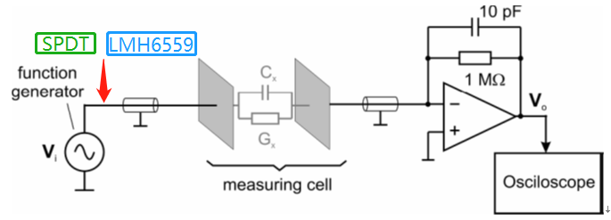
Fig.1 Circuit connection flow chart. function generator—SPDT—LMH6559—Capacitance and resistance-OPA656
Fig.2 OPA656 circuit design schematic
Fig.3 OPA656 data sheet ,Wideband, High-Sensitivity, Transimpedance Amplifier
Well, if you are really driving the test cell with an LMH6559, that low impedance output -
1. will have stability problems in the buffer driving a cap load - might want a small series resistor to isolate it from the test cell capacitance
2. The buffer output impedance will look like an impedance in series with the cap. Being inductive, the simple Zt design might not work - what signal BW are you after here?
Hi Michael Steffes,the following is Tina simulation
1.there is a series resistor between the buffer and measuring cell
2.the measuring cell is composed of cap and resistor in parallel
and it really does not work
please give me some advice to solve those problems
1.how to choose the value of CD
2.how to design the buffer circuit
and there is not real value of cap and resistor in parallel in measuring cell
Cf:0.057~4.595 pF
Rf:100-1000Ω-
So what are you trying to do? is the signal current that makes it through the measuring cell your info of interest? Looks like it since it is AC couple out of the Buffer. Incidentally, the BUF602 is a 1GHz buffer with that midscale bias stuff built in as a lower noise way to do that.
If you have the TINA file, can you attach?
Hello,
Cd is the diode capacitance of a trans-impedance amplifier. This capacitance isn't added into the circuit, but exists as a result of using a photo-diode at your input. As Micheal mentioned, we need more information on what you are trying to achieve, and it would help if you could attach the TINA file you have been using.
Best,
Hasan Babiker
Closing this thread due to inactivity. If further support is needed, please reply or start a new thread.
Thank you,
Hasan Babiker