This thread has been locked.

If you have a related question, please click the "Ask a related question" button in the top right corner. The newly created question will be automatically linked to this question.

XTR117: Minimum input resistor value

Part Number: XTR117
Other Parts Discussed in Thread: PGA309, XTR115

Good morning,

We are designing a new product using the XTR117 IC.
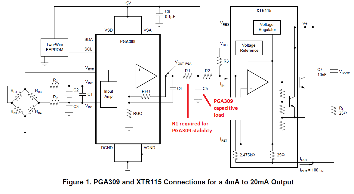
Everything works as intended but I recently read this line from "Application Report SBOA107B Using the XTR115 with the PGA309 to Generate 4mA to 20mA Output" : a minimum value of R2 = 10kΩ should be used to insure the XTR115 stability.

Here is the related schematic :

I do not see any mention of minimum value for this resistor in the XTR datasheet and since we are using a similar schematic I wonder if this information applies to the XTR117 and is up to date?
Our prototype design is using a 1k resistor and we do not have any stability issue at the moment but should we consider redesigning that part for higher resistor value ? Is there a true risk by using 1k input resistor value that could leads to instability in some boards (I know that this change seems trivial but it will imply modification of our PCB and then internal cost/delay before production)?

Best regards.

  • Hi Robin,

    The first sentence of SBOA107 on section 3.4 "Example 6: Component Selection Filter Between the XTR115 and the PGA309"  is unclear or perhaps inaccurate; although the recommended circuit is correct. 

    Resistor R1 (instead of resistor R2) is required to be large enough to stabilize the PGA309 amplifier while driving capacitor C5 (21nF).  Essentially, resistor R1 is used both to form a low pass filter, as well as to isolate the C5 capacitive load from the PGA309 output.  Most amplifiers can become unstable when driving large capacitive loads, and resistor R1 helps compensate the PGA309 amplifier while driving the 21nF capacitive load.

    The addition of resistors R1+R2 is defined from the current input requirements, and the values of R1 and C5 are chosen to set the corner frequency of the filter. 

    In your case, setting R2=1kOhm should be safe, as long as R1 is still 15kOhm (and C5 is not too large or is kept at 21nF) 

    - A recommendation is to ensure to include bypass capacitor C7=10nF on the loop supply connection in close proximity to the XTR117 loop supply connection as shown on the diagram above.

    There is a newer design including the PGA309/XTR117 with a similar filter included between the PGA309 output and XTR117 input.  It does not include a statement of the XTR117 stability.

    See below. 

    http://www.ti.com/lit/ug/slau526/slau526.pdf

    Thank you and Regards,

    Luis