This thread has been locked.

If you have a related question, please click the "Ask a related question" button in the top right corner. The newly created question will be automatically linked to this question.

OPA857: LiDAR system current pulse width design

Part Number: OPA857
Other Parts Discussed in Thread: THS4551, , LMH32401, TINA-TI

Hi team,

Customer is assessing their specification of their Lidar system.

Because of the current pulse width from sensor is about 5ns~10ns in their desired LiDAR system.

They want to check if OPA857 and THS4551 is enough for this application?

Is LMH32401 transimpedance amplifier avaliable now?

Is there any other suggestion about transimpedance amplifier and the paired high precision amp.?

Thank you.

  • Hello Feng,

       Going just based on the one specification given (5-10ns current pulse width), I would not be able to give you a definite answer. I would need more information such as input range, rise time of the pulse, and gain configurations of both amplifiers. There is a reference design that shows this same pairing with in-depth design considerations, simulations, and characterized data/plots including plots on output voltage with a 25ns pulse width at 20 and 5 kOhm gain at this link. There is also application considerations for this pairing in section 8 of the OPA857 datasheet,  The LMH32401 is available through preproduction with availability in prototype samples. 

    Thank you,

    Sima 

  • Hi Sima,

    Thank for your help.

    Their detail specification is as below:

    Half-amplitude pulse width: 5~10ns

    Rise time: 3~6ns

    Input  current range: 10e-5~10e-3A

    Output voltage range after TIA + PGA(VGA): 33mV ~ 3.3V

    I also ran their spec with TINA mode and the result is as below.

    LMH32401_simulation.TSC

    OPA857_simulation.TSC

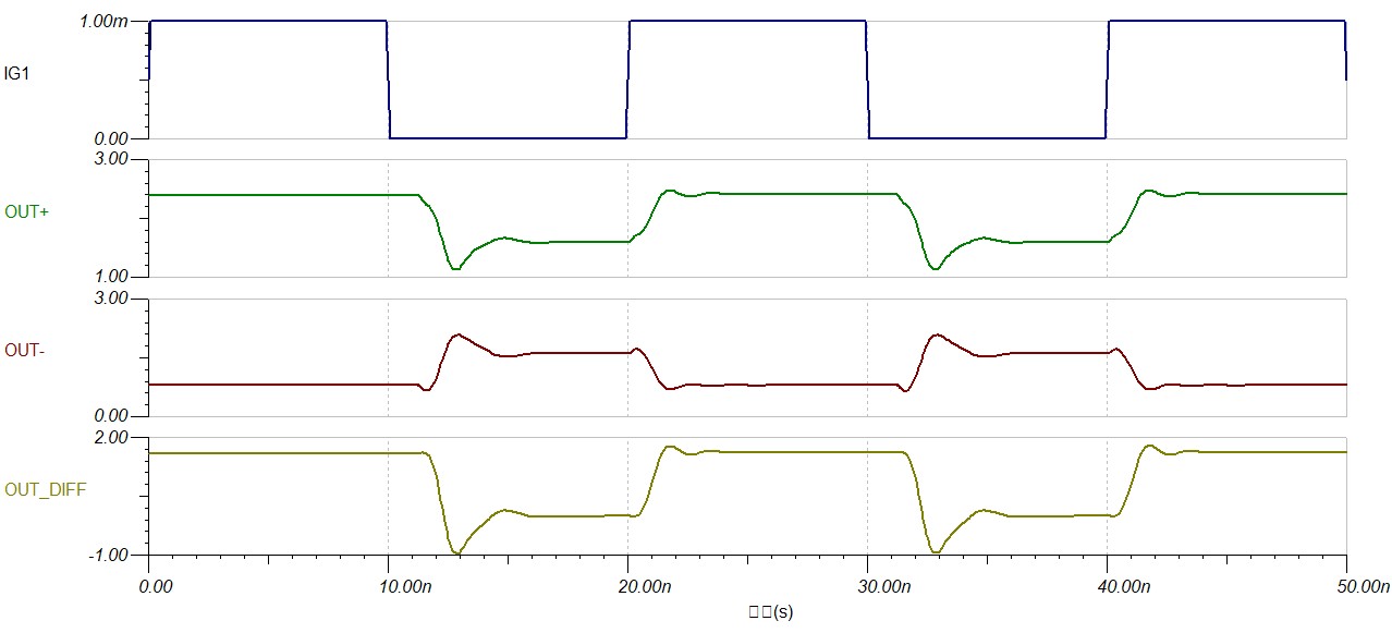
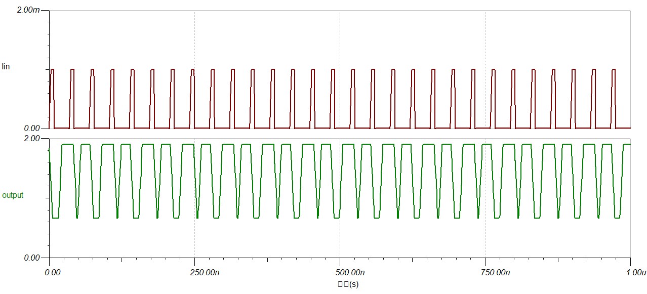
    LMH32401 result is as below:

    OPA857 result is as below:

    Please let me know if you have any suggestion for this simulation or any suggestion for this specification. Thank for your help.

  • Hello Feng,

      Thank you for attaching the Tina-Ti schematics and giving more information; they were very helpful. The LMH32401 model on the TI site was revised and will be updated within the next 24 hours. I have attached the new schematic to this post with the revised model. I added a Cpd of 1pF as recommend in the datasheet to have a more accurate representation of the capacitance at the input. I also changed the rise time of the current source to represent the information you presented me of 3-6ns. You mentioned that the input current range is around 10e-5 to 10e-3 A, which if you use the lowest gain setting of 5kOhms, you will have an output voltage of 0.05V-5V. This violates the input common mode range of 1.88 Max at a 3.3 single supply application for the OPA857. The lowest gain supply for the LMH32401 is 2kOhms which gives an output voltage of 0.02V to 2V. The absolute max voltage supply for both parts are at 3.55-3.8V. I would suggest going with the LMH32401 if the input voltage can not be lowered. 

    Thank you,

    Sima 

    LMH32401_Revised.TSC

    LMH32401.TSM

  • Sima,

    Thank for your help.

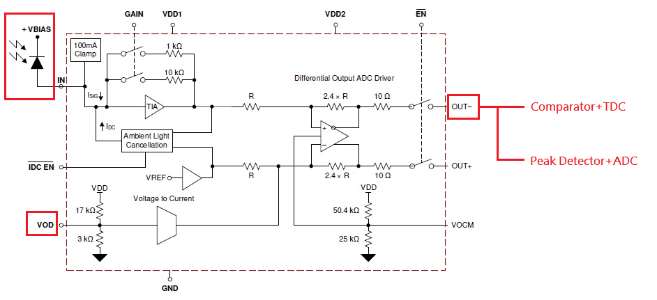
    My customer is asking that  whether they can use a current source for the input of LMH32401 as below figure due to their system architecture.

    I am not sure whether it will have some bias problem.

    • And their output of LMH32401 would pass through to comparator and peak detector. Both of them should be high impedance. I think we don't need a extra OP buffer for it. Or you have any other concern about it.
    • They only want the single end signal of LMH32401. So, just leave out+ open or anything else.

    Thank for your help.

  • Hello Feng, 

        The current source in the diagram you provided will not work as the input for the LMH32401. The amplifier has to source the photocurrent, or another way to say it would be: the photodiode can only sink current. The anode would have to be biased to a negative voltage with the cathode connected to the input of the amplifier as shown in the original block diagram. Regarding the output, you are correct with it not being necessary to have an extra buffer due to both the comparator and peak detector acting as high impedance interfaces. The LMH32401 can be used as a single-ended amplifier with the OUT- interfacing to the products you have listed. However, you will only receive half of the amplified signal at OUT- which will further split depending on the impedances of the two interfaces. Also, the SNR will be degraded due to the common mode noise adding to the total noise of the application. Regarding the VOD pin, this will depend on the desired output signal range. In order to maximize the output swing capabilities of the amplifier, an option would be setting Vocm near mid-supply and then placing VOD as low as possible without violating either voltage swing high of 2.9 V and voltage swing low of 0.36 V. If this is not necessary, Vocm could be set as high as possible; but OUT- will only swing below Vocm. Also, is the capacitance diode atleast under 10pF? I have been considering it to be around 1pF. 

    Thank you,

    Sima 

  • Hello Feng,

        Do you and the customer have any concerns regarding using the LMH32401 for their LiDAR application?

    Thank you,

    Sima 

  • Hi Sima,

    I think there is no concern now. If there is any other question I will re-the thread. Thank for your help.