This thread has been locked.

If you have a related question, please click the "Ask a related question" button in the top right corner. The newly created question will be automatically linked to this question.

OPA2188: OPA2188 current measurement accuracy question

Part Number: OPA2188
Other Parts Discussed in Thread: OPA211, OPA2192

Hi Support team 

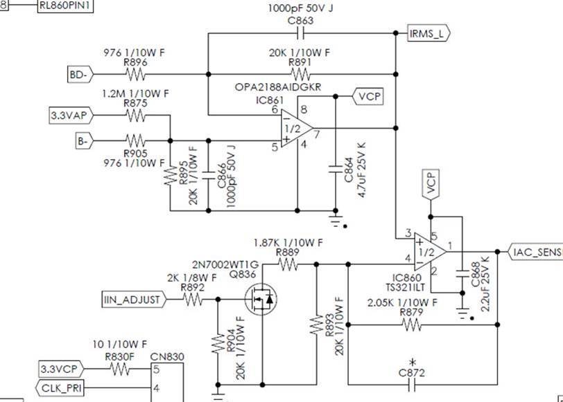
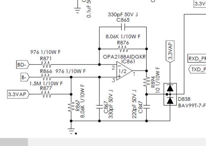
my customer adopted OPA2188 for output current measurement, the application circuit is as following

the current shunt resistor is 5mohm // 5mohm = 2.5mohm 

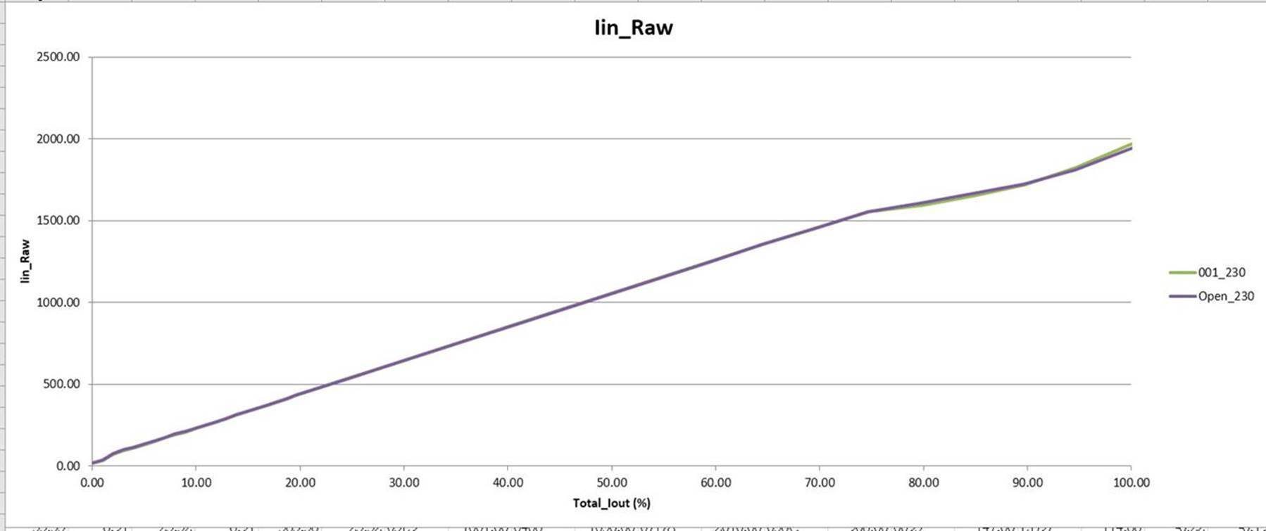
they observed that the current reporting is NOT smoothly in heavy current condition 

may i have your help to take a look and kindly advice how to make it smoothly     

  • Hello Red,

    • Is the graph taken for the top, or bottom OPA2188 circuit?
    • What is the VCP voltage level?
    • Is Iin_Raw amperes, or milliamperes? AC or DC?
    • How does the Total_Iout (%) relates to OPA211 output voltage (Vo = Iin_Raw x Ishunt x 8.06 K/976)?

    An test that might be tried to determine where the issue lies would be to install an OPA2192 e-trim op amp, in place of the OPA2188 auto-zero op amp. If the non-linearity in the output is eliminated, then it might be traced to something associated with that particular op amp topology.

    Regards, Thomas

    Precision Amplifiers Applications Engineering

  • Hi Thomas, 

    1.  Bottom 

    2. 12v with linear

    3. 0.6~0.9A for “m “ac  

    4. 0.25~0.35A

    5. what is the different with the two OPA from spec (OPA2192 & OPA2188)


    thanks a lot 

  • correct the information

    1.the shunt resistor is 10mohm//10mohm = 5mohm

    2. what we found the pin IRMS_ & IAC_SENSR are non-linear

  • Hello Red and Will,

    Thank you for the information you provided. Do note that I incorrectly typed OPA211 in the final question, when I did intend to type OPA2188.

    I am still not clear on the Iin_Raw current scale used in the graph. Answer 3 indicates Iin_Raw is about 0.6 to 0.9 Amperes, ac (RMS?) and as Will added the shunt resistor is 5 milliohms. If 0.6 to 0.9 Amperes is the current level, then the corresponding voltage drop across the shunt resistor would be 3 mV to 4.5 mV. This would be the differential input voltage applied to the OPA2188 difference amplifier circuit. It would be amplified by the stage gain of 8.258 V/V. The output would change from about 25 mV to 37 mV over that input current range. I am not this is correct so please clarify.

    You mention in a response that the non-linearity is only showing up on the lower circuit. Can you tell me the following about this circuit?

    • Is the OPA2188 connected as a high side, or low side current shunt monitor? If you can show the shunt and the circuit it connects to that would be helpful.
    • What is the range of output voltages expected at OPA2188 pin 1, for the corresponding range of Iin_Raw shunt current?
    • What is the voltage at B- or BD- when the shunt current is varied over its entire range?
    • Is the shunt current flow direction from terminal B- to BD-?
    • Does the linearity problem ever happen in the upper OPA2188 circuit at pin 7? The gain of that stage is +20 V/V and it does not have the dual diode clamp circuit at its output so it has different operating conditions.

    Even though this appears to be related to the OPA2188, it may be due to an application condition.

    Thanks, Thomas

    Precision Amplifiers Applications Engineering

  • Hi Red,

    Since we have taken this discussion internal let's close this e2e.

    Thanks, Thomas

    Precision Amplifiers Applications Engineering

  • Hi Red,

    I'm sorry, but this is a vey imcomplete presentation of your problem. Reading your post is no fun. And it's impossible to help.

    Kai