Good morning,
I have a big problem with using the INA226 module.
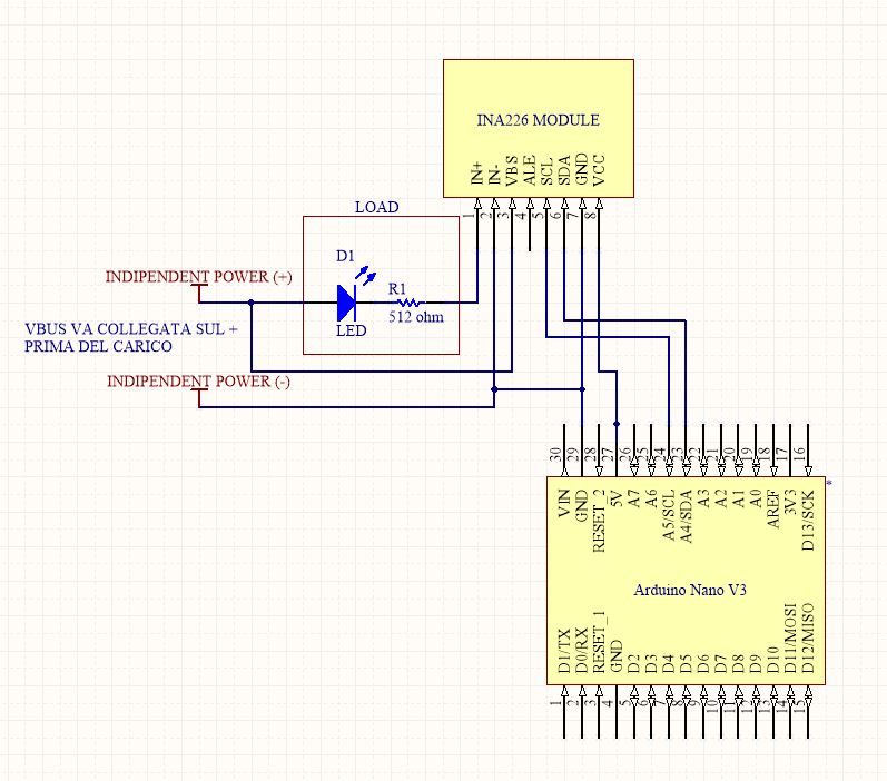
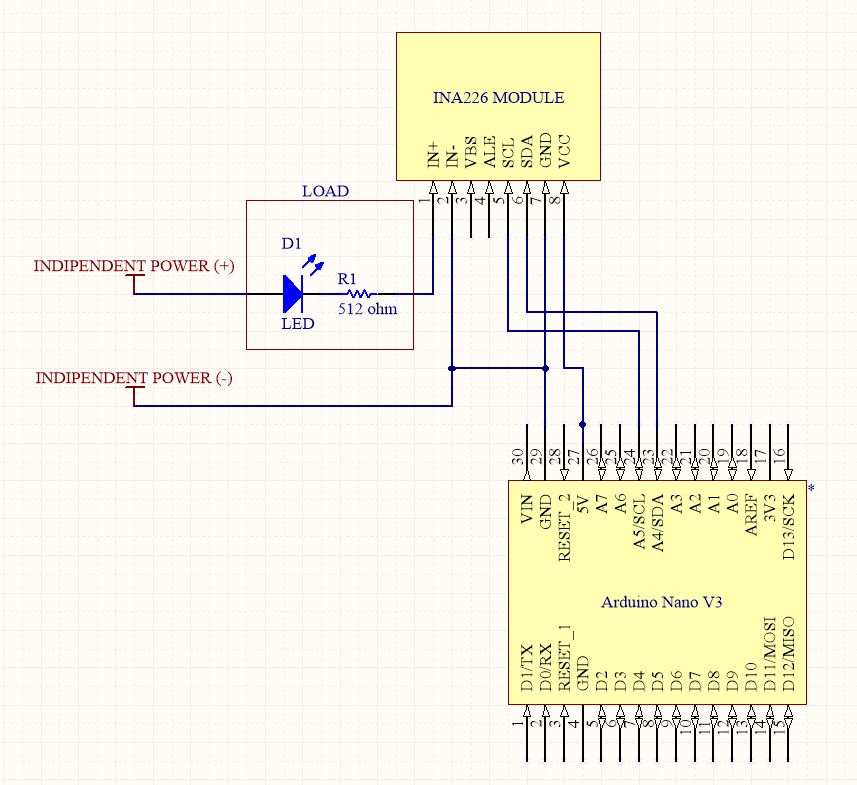
I am attaching the connection diagram and Arduino code to see if you can help me.
My purpose is:
- read the voltage (up to 12V) on the load with good precision (also OK with 0.01V) (ie not the voltage on the Rshunt but that of the user; that is, in my case, the LED Voltage + Resistance Voltage which would then be those useful for the projects)
- read the current (up to 8A) passing through the load (with a precision of 0.0005A (ie 0.5mA)).
I have already read that to be precise what matters is the Shunt resistance and I have already ordered the one suitable for my case (ie a 10 mOhm), but my problem is precisely the programming code that does not return to me what Arduino does I look for.
From the Arduino Serial Monitor I read this:
I enclose:
- Arduino code
/*
    INA226 Bi-directional Current/Power Monitor. Simple Example.
    Read more: www.jarzebski.pl/.../cyfrowy-czujnik-pradu-mocy-ina226.html
    GIT: github.com/.../Arduino-INA226
    Web: http://www.jarzebski.pl
    (c) 2014 by Korneliusz Jarzebski
*/

#include <Wire.h>
#include <INA226.h>

INA226 ina;

void checkConfig()
{

  Serial.print("Max possible current:  ");
  Serial.print(ina.getMaxPossibleCurrent());
  Serial.println(" A");

  Serial.print("Max current:           ");
  Serial.print(ina.getMaxCurrent());
  Serial.println(" A");

  Serial.print("Max shunt voltage:     ");
  Serial.print(ina.getMaxShuntVoltage());
  Serial.println(" V");

  Serial.print("Max power:             ");
  Serial.print(ina.getMaxPower());
  Serial.println(" W");
}

void setup()
{
  Serial.begin(115200);

  Serial.println("Initialize INA226");
  Serial.println("-----------------------------------------------");

  // Default INA226 address is 0x40
  ina.begin();

  // Configure INA226
  ina.configure(INA226_AVERAGES_1, INA226_BUS_CONV_TIME_1100US, INA226_SHUNT_CONV_TIME_1100US, INA226_MODE_SHUNT_BUS_CONT);

  // Calibrate INA226. Rshunt = 0.1 ohm, Max excepted current = 4A
  ina.calibrate(0.1, 4);

  // Display configuration
  checkConfig();

  Serial.println("-----------------------------------------------");
}

void loop()
{
  Serial.print("Bus voltage:   ");
  Serial.print(ina.readBusVoltage(), 5);
  Serial.println(" V");

  Serial.print("Bus power:     ");
  Serial.print(ina.readBusPower(), 5);
  Serial.println(" W");


  Serial.print("Shunt voltage: ");
  Serial.print(ina.readShuntVoltage(), 5);
  Serial.println(" V");

  Serial.print("Shunt current: ");
  Serial.print(ina.readShuntCurrent(), 5);
  Serial.println(" A");

  Serial.println("");
  delay(1000);
}
- Result on the Serial Monitor
Initialize INA226
-----------------------------------------------
Max possible current:  0.82 A
Max current:           0.82 A
Max shunt voltage:     0.08 V
Max power:             29.49 W
-----------------------------------------------
Bus voltage:   0.03500 V
Bus power:     0.00000 W
Shunt voltage: 0.00045 V
Shunt current: 0.00460 A

Bus voltage:   0.03625 V
Bus power:     0.00000 W
Shunt voltage: 0.00046 V
Shunt current: 0.00460 A

Bus voltage:   0.03375 V
Bus power:     0.00000 W
Shunt voltage: 0.00045 V
Shunt current: 0.00460 A

Bus voltage:   0.03625 V
Bus power:     0.00000 W
Shunt voltage: 0.00045 V
Shunt current: 0.00460 A
- image of the electrical connection diagram (Arduino USB power supply of the PC, while the LED is powered by an external StepDown about 5V)
Please help me.
Thanks