This thread has been locked.

If you have a related question, please click the "Ask a related question" button in the top right corner. The newly created question will be automatically linked to this question.

TL082: Trying to use transformer in my TINA TI simulation - got errors

Part Number: TL082


Hello,

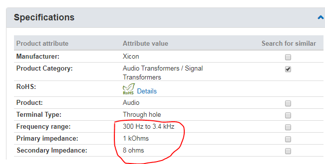
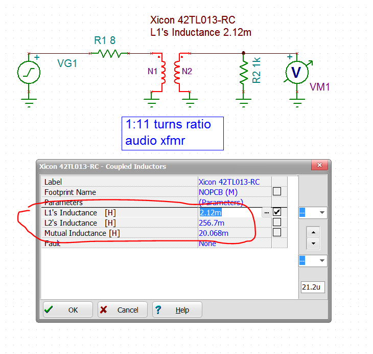
I'm trying to simulate this circuit because it has a transformer in it:

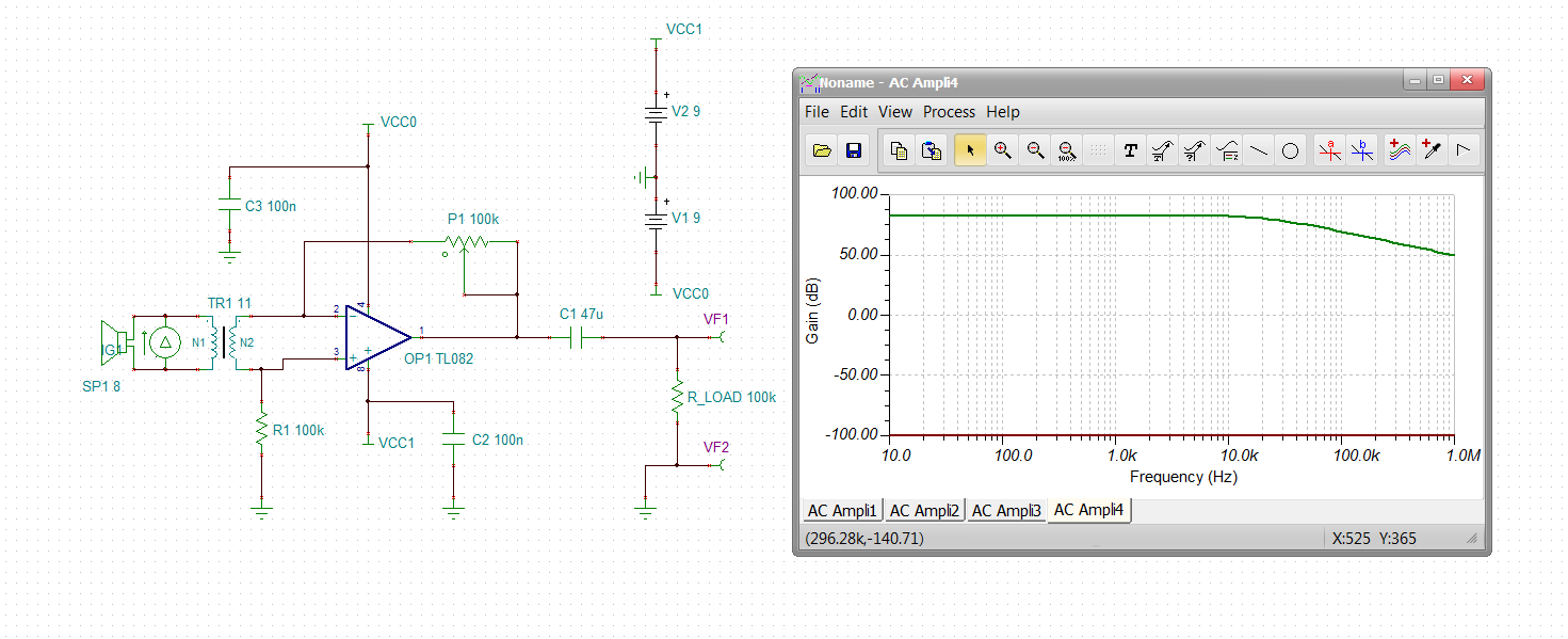
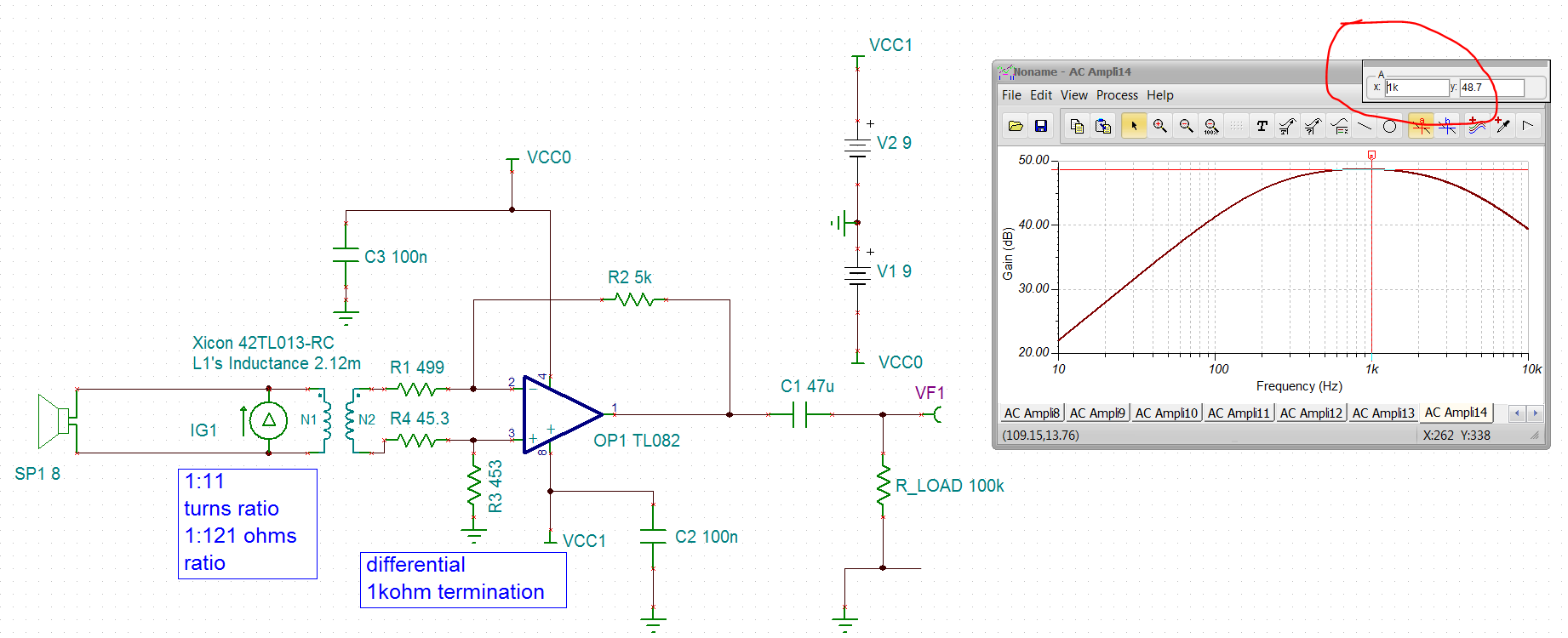
And here's my simulation in TINA TI:

But when I try an initial ERC analysis I get the following warnings:

- Pin Prim1 of Ideal Transformer TR1 is floating (This node will be grounded)
- Pin Prim1 of Ideal Transformer TR1 is floating (This node will be grounded): Pin 2 of Loud-speaker SP1 is floating (This node will be grounded)
- Pin Prem2 of Ideal Transformer TR1 is floating
- Pin Prem2 of Ideal Transformer TR1 is floating: Pin 1 of Loud-speaker SP1 is floating

Since I'm new to this I don't understand what's wrong with this. Can you please help me out here?

Here's the .TSC file if you want to play with it.

The goal of the simulation is to learn to use transformers and also to see what would be the gain in a frequency range 50Hz - 15kHz.

Thank you.

  • Worked for me (V11), but I think you probably need some series R's out of the secondary to reflect a good R across the speaker - the top side is connected to a virtual ground, not good I don't think, 

  • Sorry, didn't get this "you probably need some series R's out of the secondary to reflect a good R across the speaker". I've recently started so I may not know things...

    Another question - does TINA 11 have a free version?

    Thank you.

  • V11 is a purchase version - they have newer ones now, about $180

    Transformers transform impedance, here is the impedance sim across your speake, the transformer is moving the low impedance of the inverting summing junction into parallel with your 8ohm speaker. This dBohm plot shows .028ohm at 13Hz, and 3.5ohm at 11kHz. no likely going to make whatever is driving that speaker very happy. 

  • Well, that's still a rocket science to me. But thank you, I'll try to figure that out. The gain on your first reply looks good though!

    I'm going back to reading. And I'm buying a TINA.

  • Hello Alex, 

    The purchase version includes a number of nice things - an industrywide model database is one, took me awhile, but that tiny icon in the upper right lets you search by part number easily (transistors, diodes, op amps etc etc) It also includes Monte Carlo capability - which I use for active filters a lot, 

    Where did you get your transformer model? that is a pretty high turns ratio which will reflect the differential impedance on the secondary divided down by n^2. Some step up is fine, that much seem problematic. 

    Using a newer TINA requires you to save the files as earlier versions to share with TI, I use V9 which is a file type option. 

  • Here is your ckt modified with termination and differential gain of 10V/V. I am not at all familiar with audio versions of this type of app, but this is a step forward. Lots more experience in more RF balun coupled amps. This looks like an ideal transformer, normally the model I use is an input side inductor, output side and a coupling coefficient - those terms inject a bandpass into the simulation that is more real. differfential termination audio balun amp.TSC

  • Yesterday I made a prototype on a breadboard according to the original circuit. It does work but it's a bit noisy, probably because of wires...

    I used this transformer - 42TL013RC. It looked more or less suitable.

    I'm not sure how to assess the result though as I don't have an oscillator (oh, they're expensive!).

    I'll try the suggestions you posted in other replies tomorrow. Interesting to see how it's going to change!

  • Hey Alex, thanks for the transformer link, I guess that is a 1:11 turns ratio!!, Just by chance I had set it up with the specified 1kohm secondary, 

    Somewhere, I have a little transformer model tool, let me see if I can construct a simple TINA model for this to put into your sim - the idea with it is to hit that 300Hz to 3.4kHz span. 

  • Here you go Alex, 

    I created a small signal model for that transformer, not very flat through the passband, 

    Here are the coupled inductor model elements, 

    And the 8ohm to 1kohm specified conditions response shape, 

    And putting this in with the TL082 circuit (and correcting the R values into the V+ input), I am running this with a current source stimulus since I don't have your driver ckt, so this is an impedance gain - peak at 1kHz, 48.7dBohms (272ohms). 

    And actually, the 499 ohm into the V- input is an active impedance path so it is not quite accurate, not going fix for now, Could scale the op amp R's up and put a shunt R on the secondary to improve that. 

    TINA file, 

    differfential termination audio actual transformer with TL082TSC.TSC

  • Michael, thank you very much!

    I have couple of questions if you don't mind:

    1. What is the tool you used to create a transformer model? Is it part of TINA?
    2. You have R1 and R4 - what are the reason for them? I mean can you please share just an idea on why are they used? Hopefully, I'll get it when I finish the book I'm reading.

    3. On the original circuit the primary and secondary have 8 Ohm and 1k but on the transformer specs I see primary impedance and primary resistance (there are secondary's also). I believe the impedance matters for this circuit as the signal is ac. Is this correct? Why would one look at the primary/secondary resistances?

    4. You also changed the negative feedback resistance to 5k (from original 100k). Is this because of the transformer's secondary resistance value? I'm just trying to understand.

    Well, maybe my questions come up because I haven't finished the book (the first one!) yet :)

  • Well Alex, 

    I am not really an audio person, I do wonder about the basic premise of your circuit - surely this has been done before and there are established paths - I would suggest you rephrase what you are trying to do on the audio forum. 

    The details of the transformer model was just something I had sitting around for RF baluns. The textbooks make this very complicated to fill pages and pick up 2nd and 3rd order issues as if you were going into the transformer manufacturing business. Those are primary and leakage inductance based which works but is unnecessarily complicated for simulation. I am sure the audio folks have well established transformer modeling flows - ask them to be sure. 

    1. one of many private tools I developed many years ago, 

    2. I am trying to construct a diff to single op amp stage showing 500ohms looking out of each secondary side - this is a standard op amp circuit 

    3. Well you don't have to match the intended I/O impedances across a transformer - that will change the response gain and passband - the TINA model I sent will show that - I am still perplexed at what is generating your audio signal and won't that als get into this sense path 

    4. I tend to scale things down coming from high speed, better noise and less parasitic C induced phase margin loss. 

    They have marked this resolved, I would take the file I sent you over to the audio side and reopen starting with what you are trying to do and what is driving this speaker. 

  • Oh, this is just a circuit that uses speaker as a dynamic microphone. That's that only circuit I found that uses transformers. So the audio wave drives the speaker.

  • Alex,

    You could ground one side of the speaker/microphone directly or through 1k, 1M, or 1G ohm resistance. This won't affect the simulation results. It will make the simulator happy. With the input side floating, the simulator can't find a DC voltage solution for the left side as any value of voltage is equally valid.