This thread has been locked.

If you have a related question, please click the "Ask a related question" button in the top right corner. The newly created question will be automatically linked to this question.

INA200: Resistor and FET selection for High side overcurrent shutdown

Guru 19575 points
Part Number: INA200
Other Parts Discussed in Thread: INA201, INA203, INA206

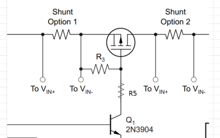
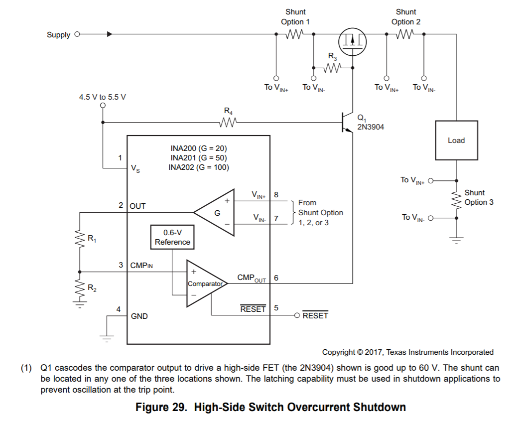
I interested in current shunt monitor with High side over current shutdown, INA200 datasheet Figure 29.

Is there any document for select or calculate external component? 

If no, please let me know about equation for resistor(R1~R4) and FET value.

By the way, I will use below specification;

Vs: 3.3V

Vcm: 55V (1/2 divide from 110V)

Isense: 0A~500mA

Rsense: 100mΩ set to option 1

Best regards,

Satoshi

  • Hi Satoshi,

    R1 and R2 are determined by the ratio between comparator threshold (0.6V) and INA201 output voltage at desired trip point (0.5A*100mOhm*50=2.5V). The relationship is R2/(R1+R2)=0.6/2.5.

    We can choose R1 to be 19K; R2=6K.

    R4 can generally be 1 to 3KOhm.

    Based on your use condition, in addition to R3 another resistor, R5 is necessary. As shown below:

    The values of R3/R5 depend on the specific FET you choose. For vast majority of them, setting R3=1KOhm; R5=10K should be OK.

    These are ballpark numbers. If you feel necessary, I’ll be more than happy to do a review once you have all components selected.

    Regards, Guang

  • Guang-san

    Thank you for kind reply,

    I will choice these value you advised.

    ※R1 and R2 are change to 22kΩ and 6.8kΩ (or 15kΩ and 4.7kΩ) because unify E24 step.

    Additional question;

    Please let me know about what effective to attach R3 and R5, or relation from FET.

    Best regards,

    Satoshi

  • Hi Satoshi-san,

    The relationship between R3/R5 and FET is approximated by this equation: Vsupply*R3/(R3+R5). The goal is to keep the gate drive within range required by the FET.

    Small values for the sum of R3 and R5 are desirable for fast response; On the other hand it determines the current in Q1: Ic≈Vsupply/(R3+R5). Therefore large values are desirable in order to keep the current low, preferably <3mA.

    Based on these constraints, you should be able to determine appropriate values for R3/5 once you have a FET selected.

    Regards, Guang

  • Guang-san

    Sorry for additional question;

    When need to attach FET ON/OFF control by FPGA output (for protection function the other than overcurrent), is there any application note or information?

    I think these case recommend INA203 or INA206 (Comparator ×2), is it correct?

    ・Comp1 mean the same as INA200's comparator function 

    ・Comp2 is controlled by FPGA, Comp2 input from FPGA signal and Comp2 output to FET (need to make Or-ing circuit for Comp1 output and Comp2 output)

    Best regards,

    Satoshi

  • Hi Satoshi-san,

    If a second comparator is necessary, of course INA203 or INA206 can be selected. The comparators are fairly versatile; the datasheets go into great length explaining how to take advantage of them in various scenarios.

    I don’t entirely understand what your intention is, but you can surely control it with FPGA, probably with the help of BJT similar to above figures for level shifting.

    A search on TI web did not return relevant app notes, but you may try the same with correct key words.

    Regards, Guang