This thread has been locked.

If you have a related question, please click the "Ask a related question" button in the top right corner. The newly created question will be automatically linked to this question.

INA333: Gain is not acting as expected

Part Number: INA333


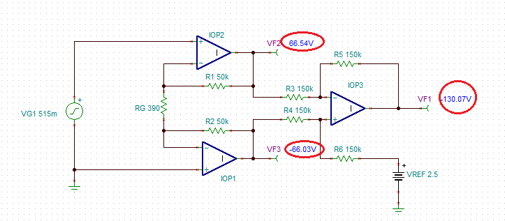
I've employed an INA333 to amplify a strain gauge's signal. I'm testing with screw 2 of the J2 screw terminal tied to 0.515V supply, and screw 3 tied to GND, rest is as shown.

the INA333 is giving me an output of 3.48V, doing the math (1+(100kohm/0.39kohm))×0.515V = 132.6V so I should be seeing V+ of 5V. I checked the supply voltage and reference voltage, both are where they should be, and adjusting the signal voltage on screw 2 up and down drives the INA333 output up and down as well, just with a significantly smaller gain than what was expected.

Where's my mistake?

Datasheet for reference: www.ti.com/.../ina333.pdf

Edit: turns out one cannot simply paste an image into the text box.

  • Jake,

    Under the conditions of your application, you not only violate the maximum differential input voltage but also grossly violate the output voltage range - see below in red circle linear voltage range.  Under such conditions the output voltage of the first two op amps inside INA333 is pushed against the opposite rails resulting in a corrupted output voltage - see below.  Also, you forgot to add Vref to your equation: Vout=(1+(100kohm/0.39kohm))×(-0.515V) +Vref = 132.566V +2.5V = -130.66V

    Please download free Output Voltage vs Common-mode Voltage calculator for INA and use it to determine allowable input/output voltage ranges.

    http://www.ti.com/tool/INA-CMV-CALC

  • Marek,


    I'm not very familiar with these amplifiers, but referencing this similar design https://e2e.ti.com/support/amplifiers/f/14/p/741275/2746837#2746837 why does that design work and mine does not? from my understanding common mode voltage is the average voltage of the two signal wires with respect to 0v, shouldnt the slider in your screenshot be at 2.5v? nonetheless even at the 5v i'm thinking it should be at the green line is instead crammed at the top of the graph.

    While i await some more guidance i'm going to change the E+ connection to 5v instead of 10v to bring the Vcm hopefully to 2.5, since E+ is the only place im seeing a meaningful difference between the two setups.

    Thank you kindly for your insight thus far,

    Jake

  • Yep, moved E+ to 5V instead of 10V and the amplifier is behaving as expected. Thanks for the assistance!