This thread has been locked.

If you have a related question, please click the "Ask a related question" button in the top right corner. The newly created question will be automatically linked to this question.

window comparator with 3 point voltage divider

Hi

I am trying to design a Window comparator circuit using engineers amplifier cookbook (SLYY137 - 03/2019) for temperature protection. I have taken a inverting and non inverting amplifier to make a  window comparator and followed the design procedure to calculate the passive component values. 

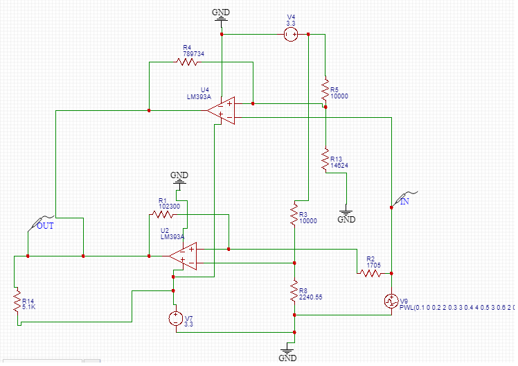
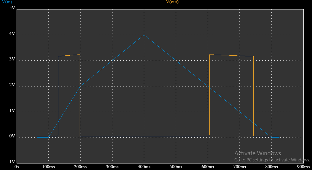
When i simulate with 2 different voltage divider as shown in figure

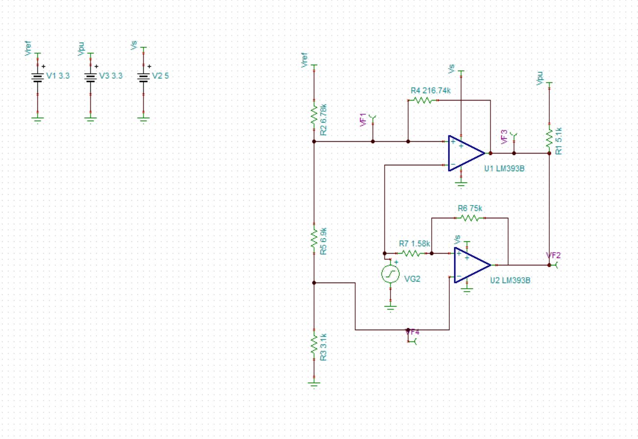
i get the expected output but when i tried doing it with a 3 point voltage divider, the comparator doesn't give expected output.

Can you please help me with this?

HT corresponds to High Temperature amplifier 

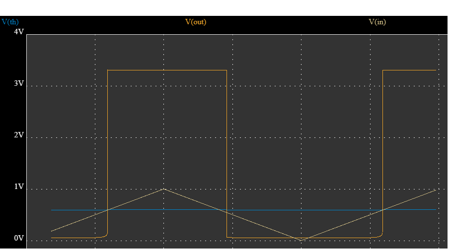
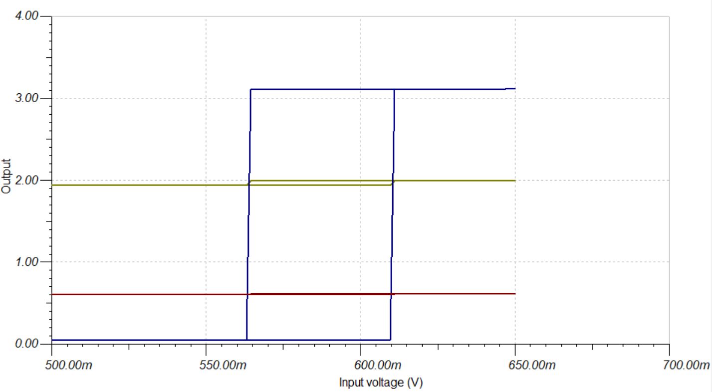
When the sensed voltage is  0.56 V output should be low and at 0.61V output be high

LT corresponds to Low temperature

When the sensed voltage is 1.99V output should be low and at 1.93V output should be high

The threshold for high temperature is 0.60V and for low temperature it is 1.96V

  • While working with tina software, the temperature sweep for NTC from 100 to 0 degree is not working. Can you tell how tosweep NTC from 100 to 0 degree?

Thank-you

Regards

B.Harini Krishna

  • Krishna

    To best assist you, please attach your TINA schematic so we can use that as a starting point.

    In addition, your high temp drawing does not make any sense.  This is a non-inverting configuration and you show the output response as inverting.  Your picture needs to be the opposite of the low temp drawing which is an inverting configuration.

    Chuck

  • Hi Chuck

    I simulated this using EasyEda software. 

    I am using an NTC as input. i need a high  at 0.61V (71 deg) and low at 0.56 V (77 deg) 

    The output for high temperature is given below

    Vth is the  threahold

    Vout is the output of the amplifier in Vin is the input of the amplifier ( output of ntc) for simulation i have used a triangular waveform this is for single comparator


    i have an output for window with seperate voltage divider for both the comparators as shown in figure

    and the output for this is 

    at 0.61 and 1.93 the out is high and 1.96 and 0.56 the out is low.

    I need to achieve this with a one 3 point voltage divider instead of different voltage divider for each amplifier. Can you help me on this?

    Here is the link to the project on easy eda.

    https://easyeda.com/editor#mode=sim,id=|52db468176b84755ba954386783d1806

    Thankyou

    Regards 

    B.Harini Krishna

  • I will investigate this further on Monday.  Sorry for the delay.

    Chuck

  • Thankyou Chuck

    Regards

    Harini Krishna

  • Harini,

    Please see the attached TINA schematic. I've designed the window comparator according to your drawings in the original post, and made the high temp sensing side of the window a non-inverting comparator.

    Regards,

    Jonny

    LM393B_WINDOW.TSC

  • Hi Jonny.

    Thankyou for the help. The design works absolutely fine. 

    Can you give me the formulas or references that you used to calculate the feedback resistor values (R6,R4) and also the values R7.

    Thank-you

    Regards

    Harini Krishna

  • Hi Harini,

    I designed the above circuit using a hysteresis tool our group created via excel. It's not designed to work specifically with window comparators, but I was still able to use it to get me in the right ball park for this design. The tool was based off the equations found in these cookbooks here:

    http://www.ti.com/lit/an/sboa313a/sboa313a.pdf

    http://www.ti.com/lit/an/snoa997a/snoa997a.pdf

    I first started with designing the low temp portion of the window. Because the voltage threshold is higher than the high temp portion of the window, we know that this side of the comparator will be on the top of the 3 point voltage divider. Using the tool, I was able to calculate R2. The tool gave me the sum value of R5 and R3 to be 10k, so I played with that divider so that the second point of my divider would create a threshold between your Vh and Vl of your high temp portion of the window.

    The tool also gives me the value of R4 to use. After verifying the hysteresis tool gave me appropriate values, I started to design the high temp portion of the window. Because this is non-inverting, you only need to worry about R6/R7 with the tool. We can set the threshold for the window divider ourselves. The tool gave me slightly different values than the ones I gave above - I had to tweak them slightly to match the conditions listed in your drawings.

    Feel free to use this excel tool in the future and let us know if you have any feedback! It's supposed to be based off the cookbook links above, but it isn't always 100% perfect. I do find it a useful tool to at least get me in the ballpark with my design values.

    8117.Comparator Hysteresis Tool.xlsx

    Regards,

    Jonny