This thread has been locked.

If you have a related question, please click the "Ask a related question" button in the top right corner. The newly created question will be automatically linked to this question.

INA128: TINA saturation simulation

Part Number: INA128

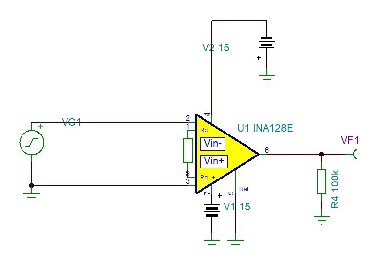
I am simulating a very simple circuit using a ac voltage source and the INA128 (image attached). I find that the amplified voltage can become arbitrarily large (if the input voltage is 1V and G=10000, I find VF1 = 10kV). Is the amplifier saturation not included in the model? If it isn't, is it possible to include it somehow?

  • Hello ,

    I have included the INA128 Tina simulation and I did not see what you observed. I configured what your input parameters, 1Vpp, Gain=10k, please see the attached file. 

    If you have further questions, please let us know. 

    Regards,

    Raymond

    INA128 12052019.TSC

  • Hello Raymond,

    thank you very much for your answer. I have performed a transient simulation using my previous design and your file, and can see the output voltage saturating indeed. However, if instead of a transient simulation I run an AC analysis (to obtain the table of AC results) and I probe Vout manually, I find around 10kV. 

    Cheers,

    Alberto

  • Hi Alberto,

    I see your point. There is an issue with the model outside of linear operating region in AC nodal analysis. The output should have capped at the supply voltage rail as shown in the Transient plot. 

    As the Vin increases from 10mV, 100mV, 200mV, 300mV and 500mV, the Vout also increases linearly beyond the supply voltage rail (set R1=505.1 Ohm or G=100), which is incorrect. 

    Regards,

    Raymond