This thread has been locked.

If you have a related question, please click the "Ask a related question" button in the top right corner. The newly created question will be automatically linked to this question.

INA233: Measurement results are unstable.

Part Number: INA233

hello everyone,

i'am using ina233 with nucleo-F429ZI. we are using board shematic:

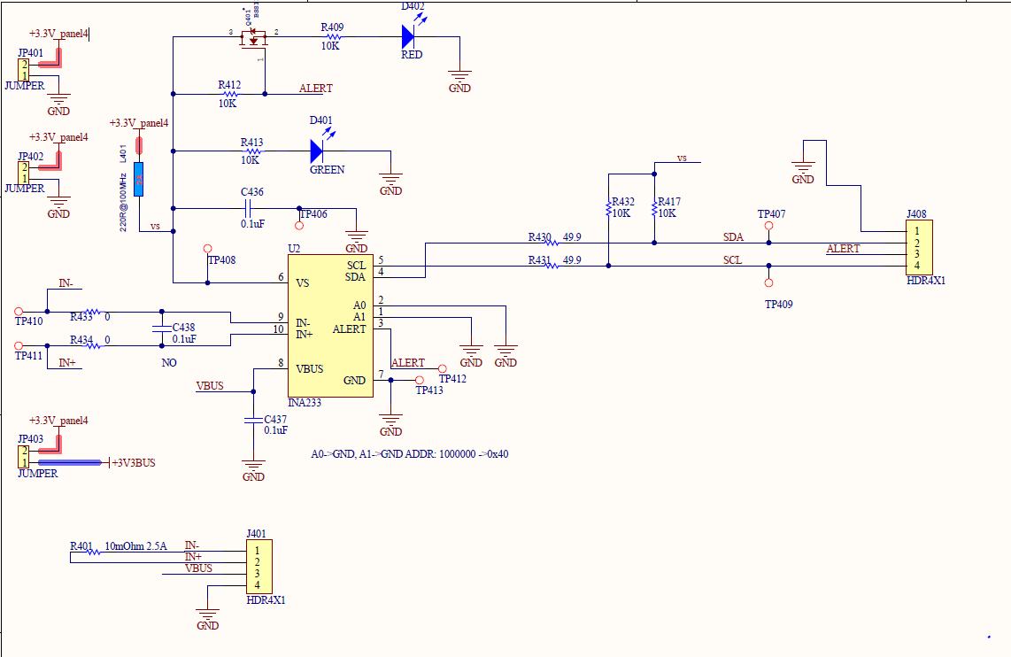
we read voltage from the default MFR_ADC_CONFIG reg settings, ina233 values ​​are constantly changing. but when we measured it with multimeter, we found that the voltage was constant.


then we took the sampling time 4ms. We have set the average bit 64. was more stable than before. but a second 4 samples are very bad. Our shunt resistance is 10mohm and we did the calibration. what to do to ensure that it does not oscillate at the default settings. I would appreciate if you help.

below you can find the code we use:

codes can be found here.

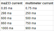
here are the measured voltage values  (1ms, no averaging operation):

  • Hello Abdullah,

    Where are you probing when you measure the input voltage with a DMM? It looks like you have test points TP410 and TP411, but they are before the input filter. If you haven't already, try measuring directly on the INA233 pins to see the true input voltage and compare that against your code readings.

    Best regards,

    Ian Williams
    Applications Manager
    Current Sensing

  • Hi Abdullah,

    a multimeter might be too slow to be able to capture the fast changes of the input signals. Scope plots would deliver way more useful information. Do you have scope plots of "vshunt" and "vbus"?

    Kai

  • thanks for replying.

    I will measure the vbus voltage with the oscilloscope. When I configured the device in this way, my guess became a little less;

    * NUMBER OF AVERAGES : 16
    * CONVERSION TIME         :  4.156 ms


    but now I have this problem. I compared the values ​​measured by ina233 with those I read on the multimeter. 

    even though I do calibration, there is a difference. 
    my operations are as follows;

    R_shunt = 0.01;
    I_max    = 2.048;
    
    C_LSB = i_max / pow(2, 15);
    P_LSB = 25 * C_LSB;
    
    *Current_LSB = C_LSB * 1000000;
    *Power_LSB = P_LSB * 1000;
    
    CAL = 0.00512 / (r_shunt * C_LSB);
    
    data2IC[0] = INA233_MFR_CALIBRATION; // start address
    data2IC[1] = CAL;
    data2IC[2] = (uint16_t)CAL >> 8;
    
    if(HAL_I2C_Master_Transmit(&hi2c1, 0x80, (uint8_t*)data2IC, (uint16_t)3, (uint32_t)1000)!= HAL_OK)
    {
        printf("I2C:WrErr %d\n\r", HAL_I2C_GetError(&hi2c1));
    }
    
    HAL_I2C_Mem_Read(&hi2c1,INA_ADDR,INA233_READ_VIN,I2C_MEMADD_SIZE_8BIT,(uint8_t *)inaBuff,2,0xFFFF);
    
    HAL_Delay(100);
    
    value = inaBuff[0];
    value=((inaBuff[1] << 8) | value);
    
    vbus=(value*pow(10.0,-R_vb)-b_vb)/m_vb;

  • Hi Abdullah,

    how have you connected "Vbus" with the "shunt"? And what is the "load"? And what about the jumpers? How are they set? And is "+3V3bus" identical with "Vbus"? And what means the red and blue highlighting? All this is very confusing to me!

    Please assemble the INA233 so that you get a true and real application. Then make the measurements with clean, stable and noise-free DC currents and DC voltages.

    If there is a certain chance that you have already damaged the INA233 during your previous experimenting, I would recommend to start with a fresh INA233.

    Kai

  • Hi Abdullah,

    It's been some time since your last post. I hope your issue has been resolved. If you need more help, please reply with the answers to our questions and we are happy to help with your troubleshooting.

    Best regards,

    Ian Williams
    Applications Manager
    Current Sensing