This thread has been locked.

If you have a related question, please click the "Ask a related question" button in the top right corner. The newly created question will be automatically linked to this question.

Switching a 0-28V pulse in less than 10ns

Other Parts Discussed in Thread: THS3491, TINA-TI, THS3062, THS3095, LM7171, BUF634A

Hello,

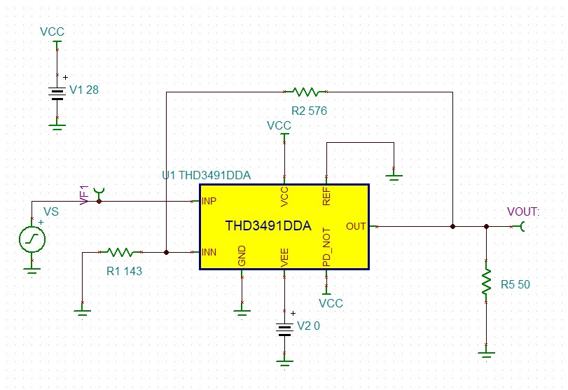
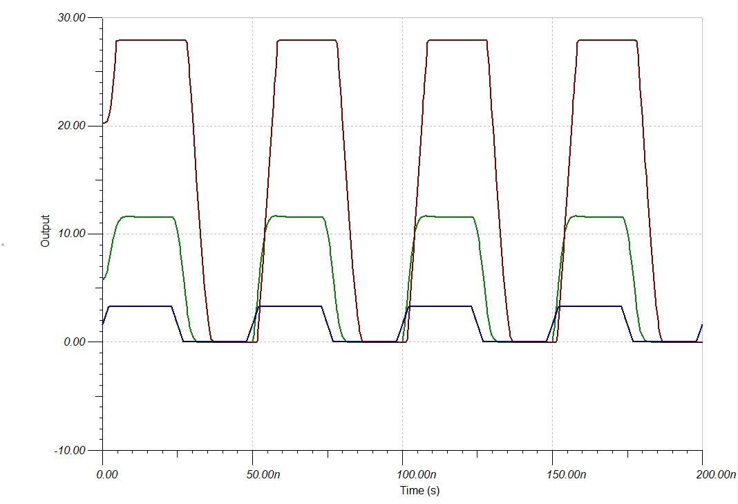
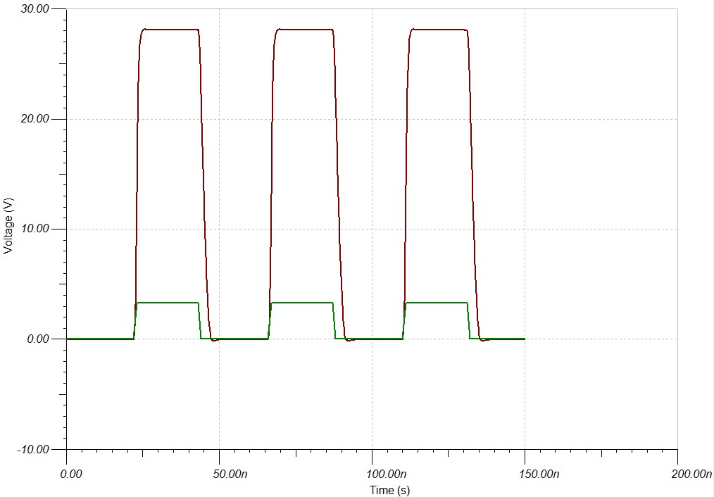
In my project I would like to switch the output of 0-28V pulse in less than 10ns. The rise and fall times should be less than 10ns.

A XILINX FPGA shall drive the circuit.

I tried to switch a BJT with a Baker Clamp, but I couldn't achieve this 10ns requirement.

I would appreciate any help

Kind Regards

  • Morning Kerem, 

    Odd you should ask, this is actually the topic of an upcoming article - 

    Use the THS3491 running inverting on a -2V to 30V supply. If you need to buffer your source to drive the input R, do so using a very fast device as well (need a very low broadband source impedance at both extremes)

    Here is a excerpted plot in an Jan 7, 2008 article to post up on Planet analog. This is showing up to 20V steps, but the THS3491 on 32V total can do a 28V step. The right plot is the extracted point slope showing no slew limit and peak dV/dT of 15000V/usec. And this was actually a gain of +5V/V so maybe non-inverting would be ok for this as well, at higher gains, 

  • And actually the headroom limit will be on the input buffer, may need to massage a little bit to get this work, but the raw output slew rate is there. 

  • Hi Kerem,

    what is the load?

    Can you tell more about your application?

    Kai

  • Yes Kerem, 

    Can you tell us your exact input swing and required loading along with the desired output loading. 

  • Thank you very much for your valuable responses.

    The output of the buffer is fed to a 50 or 75Ohm 1 meter long coax cable to a 10k input comparator.

    I am not sure what the other circuit will do, but they require to receive 0-28V pulses as short as 50ns. Therefore I need really short rise and fall time.

    The input to the circuit is LVCSMOS3V3 an FPGA output pin.

    I may have a push-pull buffer before the high speed buffer. OR should I? I am not sure

  • Well you obviously have a cable transmission line problem here as well, 28V input comparator?? Not sure about this one? 

    Might really want some kind of HighV switching ckt that can drive the cable capacitance without stability issues or insertion loss due to matching. 

  • Thank you very much for your help.

    I checked THS3491 current feedback amplifier, as far as the slew rate is concerned it is perfect for my application.

    I downloaded the TINA-Ti example for the THS3491DDA part.

    However, I can not get the outputs that I would expect when I do the simulations.

    As I mentioned before I have a really fast 3.3V pulses from the FPGA I'm using.

    I couldn't really figure out the amplifier configuration. I would appreciate if you could help me

    Kind Regards

  • Hello Kerem,

    Could you please provide your TINA-TI circuit and details on how the output is varying from what you expect? What issues are you having with the amplifier configuration?

    Best,

    Hasan Babiker

  • Dear Hasan,

    Thank you very much for your help.

    I am implementing a basic non-inverting amplifier with THS3491. Supply is Vcc = 30V and Vss = 0V.

    I dont need a maximum swing, so I did not include any bias to the amp.

    The input is a 0-3.3V pulse with varying pulsewidth.

    I would appreciate if you could help me

    Kind Regards

    Kerem

    THS3491DDA_10ns.TSC

  • Hello Kerem,

    The major issue here is the input and output limitations of the THS3491. Your input should be at least 4.1V away from either supply, so an input of 0V-3.3V is entirely outside of the usable input range. Your output has a headroom of at least 1.5V from either supply, this headroom becomes larger when a large output current is used. Because of these reasons, I would suggest biasing your circuit to midsupply as I have done in the attached TINA circuit below.

    This circuit will give you a 28V pulse with no load or a 75-ohm load to midsupply. However by referencing your load to GND, your output current and therefore the output headroom will increase and you will not be able to reach your desired 28V pulse. 

    Kerem.TSC

    Best,

    Hasan Babiker

  • Dear Hasan,

    Now that I figure out why the circuit of mine didn't work at all. Thank you very much for your help.

    I figured  that THS3491 would not work for my application, after having understood the working principles with your help.

    I would appreciate if your could comment on the following points.

    My application is to amplify a 0-3.3V pulse with varying pulse width and period coming from an FPGA. Even more the the requirement is that I should be varying the output voltage of the amplified pulse from 5V to 28V. And lastly the requirement is that the rise and fall times of the pulses should be less than 10ns.

    I designed a variable output power supply from 5V to 32V, having a digital control.

    1. I thought that I could vary the output of the power supply and use the amplifier saturated, to get the desired voltage level of the pulse.

    2. With THS3491 the single supply could not drop no less than 14V, which is a problem

    3. To bias the signal mid point between the positive supply, I need to have decoupling cap between the FPGA and the amplifier. And this wouldn't work because I have varying pulse. And I can not supply a DC voltage to the FPGA. IT would damage the output.

    4. If I use the amp in dual supply mode I can not go up to 28V.

    I need a very fast slew rate amplifier for sure for the rise and fall times of the amplifier. To my understanding the CFA in my application wouldn't work. 

    Is that correct? Or could I use THS3062 or THS3095 instead? with a negative supply of -2V the simulations results look good.

    So what would you recommend me with my application. I checked the fastest VFA and found LM7171. Did couple of simulations looks promising.

    For single supply operation, I do not have to supply an bias. GBW product would be a problem when operating saturated, but for this I shall try cascaded amplification to have higher bandwidth. Also the output might not drop down to 0V, for this I could supply a small negative voltage.

    Thank you again for your help. It would be great if you could also comment on these points too.

    Kind Regards

    Kerem Oktem

  • Hello Kerem,

    Could you please provide the simulations that you are referring to? The major issue I see is that while the parts you mentioned may have better input/output limitations compared to the THS3491, you still need the ability to provide a high output current. At 28V and a load of 75Ohms, you will need a part that can provide at least 373mA of current. Only the THS3491 has this capability, and the BUF634A can only help to around 250mA. 

    Best,

    Hasan Babiker

  • Hello Hasan,

    Actually the load shall not be low, it is expected to be at least 10k. But the output shall be connected to the load via a 1m 50Ohm or 75Ohm coax cable.

    I attach the circuit and the simulations of the parts.

    I would appreciate if you could comment of these circuits.

    Kind Regards,

    KeremLM7171_Sim.TSC  THS3095.tsc  THS3062.TSC

  • Hi Kerem,

    when driving a coax cable at least mount a series termination resistor at the output of OPAmp.

    And don't violate the common mode input voltage range of OPAmp!

    Kai