This thread has been locked.

If you have a related question, please click the "Ask a related question" button in the top right corner. The newly created question will be automatically linked to this question.

Hi, I have a question about settling time of OPAMP

Hi, I was studying about bandwidth limitation of OPAMP settling time.

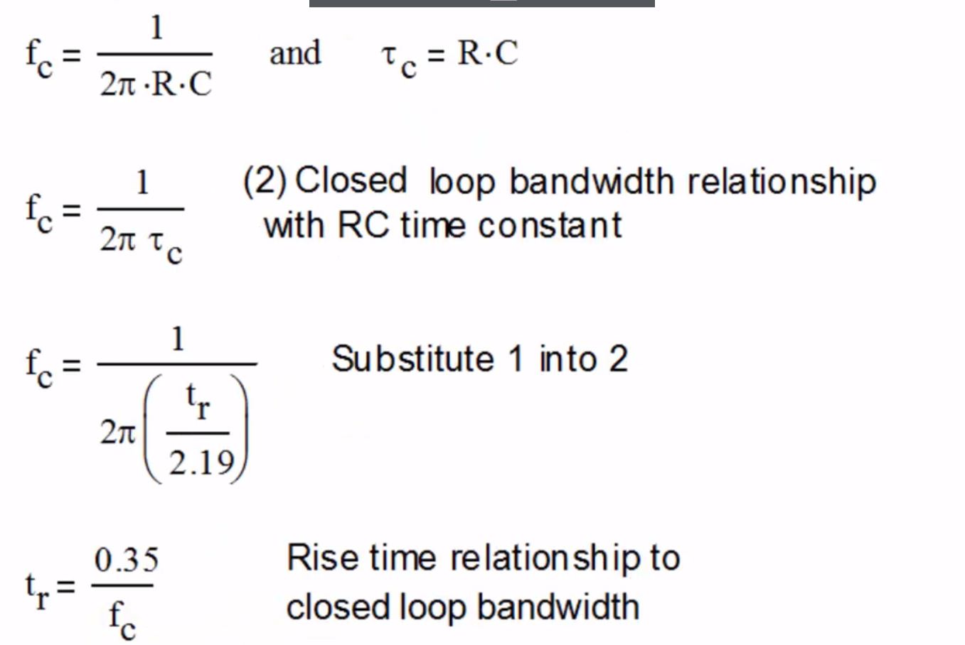
I wonder where R above equation came from.

I can understand that C is charging capacitor Cc like below.
 

Could you explain in more detail where R is from in this lecture?

and can you confirm if the above Fc is the cut-off frequency of OPAMP itself.

Thanks,

Best regards,

Yun

  • Hi Yunsik,

    where do you have these formulas from? Can you give a link?

    Kai

  • Former Member
    0 Former Member in reply to kai klaas69

    Hi Yunsik and Kai,

    The formulas are coming from a TI precision labs presentation on slew rate.  I would like to call attention to slides 14 and 15 of this presentation, which explains these equations.  The slides describe the process for deriving the rule of thumb rule for a small signal rise time.

    There's a bit of reading between the lines that most go on here, because there is some knowledge about the internal setup of an op amp that is almost assumed here, but not really discussed.  Perhaps it's discussed in an earlier video.  I will explain here.

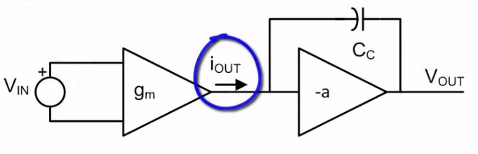
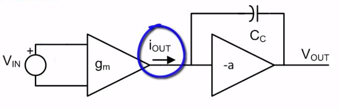
    Op amps are typically multi-stage devices, meaning the input signal will pass through multiple transistors from input to output.  In this presentation, a first-order approximation is used.  The slide shows a two-stage model.  On the left is the first stage, which is represented by a differential input pair.  The second stage, on the right, is represented by a gain stage (the triangle) which is gaining up the output signal.  Across the gain stage is Miller capacitor, which is used to help stabilize the amplifier.  The miller capacitor helps to ensure that the amplifier has a single, dominant pole.

    Now let's look at the slides.  On the first slide, we define the rise time.  We then understand that the time it will take to get the output to its final value is related to the charging time of a capacitor.  We solve for the rise time in terms of tau, which is the time constant of a charging capacitor.  The time constant for a charging capacitor is equal to the resistance seen by the capacitor multiplied by the capacitance.  Remember, the amplifier has an output impedance/resistance.

    On the second slide, we see the equivalent equation for the amplifier's closed-loop bandwidth.  From the slides, fc is the closed-loop bandwidth.  The system is approximated as a single pole, which is formed by a single RC.  So, that's where the first equation comes from.  RC is equivalent to tau.  So we can substitute the equation from the first slide onto the second slide.  Algebraic simplification then gives us the final answer.

    Hope this helps.  Let me know if anything is unclear.

    Regards,

    Daniel

  • Hi Daniel,

    Thank you for your detail answer.

    I can understand how to calculate the settling time.

    I think i do not get what exactly R is.

    You said R is the resistor seen by Cc.

    Then, R is the output impedance of first-stage of OPAMP?

    Also, If i understood OPAMP closed loop correctly, OPAMP closed loop cut-off frequency is related to noise gain like above picture.

    Then, if feedback resistor changes then first-stage transistor's output impedance also changes?

    Thanks,

    Yun

  • Former Member
    0 Former Member in reply to Yunsik Chung

    Hello Yun,

    I think it's important to point out here that these formulas provide only a first order approximation.  It's not exact.

    For example, we approximate the output response of the amplifier as a charging capacitor.  But, there is more going on within the amplifier.  We also approximate the system as a single-pole system.  For this reason, we say that the closed loop bandwidth is approximately determined by an RC pair.  This is not an unreasonable approximation, but the system is really a combination of multiple poles and zeroes.

    Having said that, let me now try to answer your question.  As for "R", it is not pointing to any specific impedance in the system.  It is a placeholder to describe the overall response at a high level.

    Your closed loop bandwidth formula is correct.  The feedback resistor will not change the first stage output impedance.

    Regards,

    Daniel

  • Hi Daniel,

    I got the concept.

    Thank you very much!

    Best regards,

    Yun