This thread has been locked.

If you have a related question, please click the "Ask a related question" button in the top right corner. The newly created question will be automatically linked to this question.

INA200: INA200 output failure

Part Number: INA200
Other Parts Discussed in Thread: INA240, INA381, INA293, INA303, INA302, INA301, INA300, INA290-Q1

Hi,

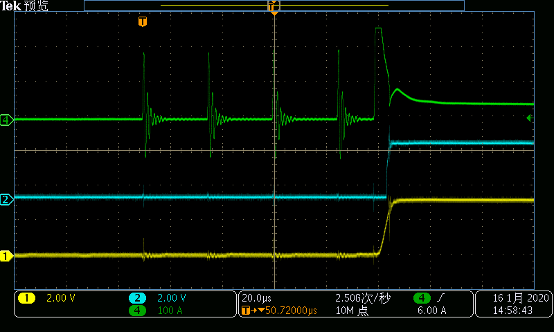
When using INA200 for short circuit current sensing,the output of amplifier(Vbus) is wrong.

As shown below,there are two possible reasons.

1. The duration of the first four current pulses is too short.

    It's about 1~2 us.

2. Reverse current affects current detection.

   The current on the sampling resistor oscillates continuously in the bidirectional direction

Please help to analyze the possible reasons,Thanks.

Channel 1:Vbus

Channel 2:SC_N

Channel 4:R1's Current

  • Hey Eric,

    Thanks for the question.

    Well there are couple things working against this circuit.

    First, the oscillation of the current is about 500kHz, which is right at the edge of INA200's BW capability.

    Secondly, the current is starting at 0A, which means the amplifier is starting out saturated. This means if the amplifier is to respond to a current jump, then there will be a delay for it coming out of saturation. This is usually called an overload recovery delay for many amplifiers.

    Thirdly, the current is oscillating bidirectionally as you point out. When the current goes negative, the shunt voltage goes negative, and this saturates the INA200 even more severely than when Vshunt =0V. When Vshunt is negative, the amplifier tries to drive its output below ground, but it can't because it is a single-sided supply device and it can't drive any lower than its ground. So the negative current is saturating the output and creating further overload recovery delays.

    All in all, before the amplifier has time to respond to the first positive current cycle, the current goes negative and this keeps the amplifier from every driving a output voltage within the linear region. Even worse, this device's linear output operating region is not rail to rail, but rather 0.4V to Vs-0.25V. This means you need the output to always be within this region for you to achieve its BW and error specifications.

    Hope this helps.

    Sincerely,

    Peter

  • Hi,Peter

    Thanks for reply.

    For the above short circuit conditions,could you provide solutions to solve that problem?

    That circuit is used in high side (DC+) of three-phase inverter bridge.

    Thanks for help.

    Eric

  • Hey Eric,

    To best answer your question, I will need to know system-level requirements such as:

    • Does normal operating current need to be sensed or is the current sensor just needed to detect over-current?
    • What are the normal operating and maximum inverter voltage? This set the VCM rating needed by device.
    • Is the current threshold positive, negative, or both?
    • What is the response time of the amplifier needed for the OCP event?

    Here some literature explaining the devices we have to offer with functionality for short-circuit detection:

    http://www.ti.com/lit/an/sboa168b/sboa168b.pdf

    http://www.ti.com/lit/an/sboa162c/sboa162c.pdf

    http://www.ti.com/lit/an/sboa297/sboa297.pdf

    The INA381, INA300, INA301, INA302, and INA303 are best complete devices for over-current protection as they have integrated comparators. However, if you need device with a voltage rating greater than 40V, then I would look at the INA293, INA290-Q1, INA240. These are the fastest current sense amplifiers and have high voltage ratings. They would need to be paired with a comparator.

    Hope this helps.

    Sincerely,

    Peter