This thread has been locked.

If you have a related question, please click the "Ask a related question" button in the top right corner. The newly created question will be automatically linked to this question.

XTR111: Problem with low load regulation

Part Number: XTR111

We have implemented an XTR111 with 12.7V VSP (decoupled with 100n), REGF shorted to REGS, MOSFET Directly on IS/VG, and VIN is driven from a OpAmp, and swings from 0->0.6V, Rset = 330ohm (Should correspond to 0-20mA). A S1G diode is connected between drain and output in conducting direction, to protect against reverse connections. EDIT: OD is pulled to ground, /EF is floating. GND and Pad is tied to ground.


This works very well when connected to a 100 ohm load, all the way up to 500ohm, as expected - measured with a multimeter in series with the load resistor. But for load resistors from ~100 ohm down to the burden resistor in the multimeter, we get an error on the current loop. EDIT 2: To clarify; measured on a multimeter on the current input

What measures as 4 mA from 100 ohm and up, gives ~3.7mA with lower than 100 ohm
What measures as 17.5 mA from 100 ohm and up, gives 18.6 mA with lower than 100 ohm

What could be the issue here? 

  • Hi Daniel,

    the correct Rset for 20mA would be 300R, not 330R.

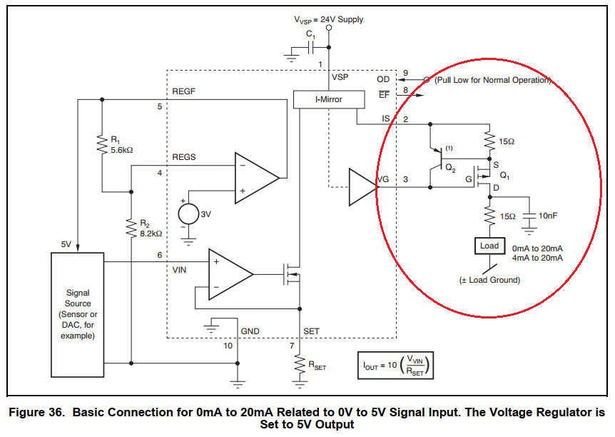
    It's strongly recommended to use the output circuitry shown in the figure below:

    This not only to protect the MOSFET, but also for guaranteeing stability in connection with arbitrary loads!

    Kai

  • Thanks Kai!

    Hi Daniel,

    Agreed with Kai. Please follow his suggestions and reply if you run into any issues.

    -Tamara

  • Hi Kai, thanks for the input.
    I'm aware of the output circuitry, and if I have to, I'll of course implement this, bit as it happens, the current design was used in a very well proven design from one of my previous employers, sold in 10's of thousands of units for the industrial market, without Q2 and the 2 15 ohm resistors. I know it works, I just need to see what I have missed. The main difference i can think of is my choise of mosfet.
    Are there any other critical parameters of the mosfet than VGS, Cgate and power dissipation capability that should be taken into account here? 


    For low loads, as we have problems with now, there will be next to no voltage drop across the IS->Source resistor, and Q2 will always be off. How else do you suggest this circuit changes the stability of the output?
    I don't observe excessive currents in the range that this current limiter is supposed to protect against - ~33mA (ref data sheet)

  • Hi Daniel,

    the lower 15R resistor and the 10nF are especially important for stability. Could you add at least these components to your design?

    Kai

  • Thanks. I'll try that, (even though it was not in fact included in the previous design.  )

    I will also try to replace the P-fet I've chosen - it was somewhat marginal in Pd. I'll keep the thread updated.

  • 15R and 10nF made no difference, and neither did the replacement of the P-FET.

    What solved it, though - was the removal of the leakage path that we had, similarly as in this support request.

  • Hi Daniel,

    thanks for the feedback.

    Can you please tell more about your leakage path, so that we can better help others?

    Kai