This thread has been locked.

If you have a related question, please click the "Ask a related question" button in the top right corner. The newly created question will be automatically linked to this question.

INA226: Confused about shunt register readings

Part Number: INA226

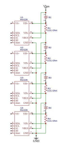
I have some confusion with values of INA226 shunt register which I've got on my test schema (can see at e2e.ti.com/.../873715).

I have schema with four loads and INA226 connected by series.
General supply input is about 5 V.
I used four resistors by 22 Ohm connected serially as load and interleaved with shunt inputs of four INA226.
Expected current in chain by Ohm law is about 5V/(22Ohm*4)=0.056A. I used 0.01 Ohm shunt resistor so voltage on the shunt should be about 0.056A*0.01Ohm=560uV, which corresponds to value 224 (0x00e0) in shunt register. But I got cardinally different values, are about 500 (with some deviations for each INA226).

Where is my mistake?

And second question - why voltage values so much differs? I checked with digital multimeter - difference can reach tenth of volt.

My calculations
Rshunt - 0.01 Ohm
Imax - 8.1975 A
LSBc - 0.00025 A/bit (rounded from 0.000250168)
Calibration register value - 0.00512/(0.00025*0.01)=2048 (0x0800)


Excpected shunt register value for 56mA
0.056A×0,01Ohm÷0,0000025V/bit = 224 (0x00e0)
Excpected current register value the same as shunt register value because calibration value.
Expected current calculation in relation to LSBc
224*0.00025A/bit=0.056A

Output of reading of sensors:

RAW shunt reg: 0xf301 499
RAW curr reg: 0xf301 499
RAW volt reg: 0xef03 1007
INA226[0x40] 1579437428: registers: shunt 0x01f3 current 0x01f3 voltage 0x03ef
INA226[0x40] 1579437428: values: current 0.124750 voltage 1.258750 ( delta 1.258750 )
RAW shunt reg: 0xfb01 507
RAW curr reg: 0xfb01 507
RAW volt reg: 0xc907 1993
INA226[0x41] 1579437428: registers: shunt 0x01fb current 0x01fb voltage 0x07c9
INA226[0x41] 1579437428: values: current 0.126750 voltage 2.491250 ( delta 1.232500 )
RAW shunt reg: 0xe501 485
RAW curr reg: 0xe501 485
RAW volt reg: 0x4e0c 3150
INA226[0x44] 1579437428: registers: shunt 0x01e5 current 0x01e5 voltage 0x0c4e
INA226[0x44] 1579437428: values: current 0.121250 voltage 3.937500 ( delta 1.446250 )
RAW shunt reg: 0x7102 625
RAW curr reg: 0x7102 625
RAW volt reg: 0x950f 3989
INA226[0x45] 1579437428: registers: shunt 0x0271 current 0x0271 voltage 0x0f95
INA226[0x45] 1579437428: values: current 0.156250 voltage 4.986250 ( delta 1.048750 )

  • Hello MYKHAILO,

    Thank you for posting your question. We hope to solve your problem soon.

    I have been looking through your information and your calculations and understanding seem correct.

    So does your DMM measurement read 56mA or 125mA?

    Could you resend your schematic? The link may be broken.

    Sincerely,

    Peter 

    Applications Team

  • Hi
    Peter, thank you for reply!

    I attached my schema at end of this message. For testing purpose I temporary use resistors as load instead of batteries.

    I have measured current in my schema with two different multimeters and one oldschool analogue tester (which with arrow). All three devices show value in range 52-58 mA with little spread.

    Also I changed shunt resistors to new in two modules which show current with most deviation from average value but without any valuable result.
    I plan to grab i2c conversation with logic analizer, but I think this haven't big chance to succes.

    I'm stuck and slightly confused about what else I can check...
    So I'll glad to any help)

    PS. I'm beginning to suspect that IC in modules are contrafact replica, is it possible? Modules bought on one wide famous chinese trading platform...

  • Hey MYKHAILO,

    Maybe what could be happening is that you are somehow appending a zero to end of the shunt register and effectively multiplying the shunt voltage and current values by 2?

    The only bits that should be used to determine shunt voltage or current are 14:0.

    Maybe you could try changing the sense current to see if the measured value remains exactly half of real current. If it does, then look over your code to make sure there is no unexpected bit shifting of the contents.

    As for the idea that these are possibly counterfeit, please make sure the distributor was an authorized TI distributor:

    http://www.ti.com/info-store/distributors.html

    You can also note what the package marking is for the IC and gather any information about the ICs lot number or lot trace code (LTC) given to buyer at the time of purchase. Package marking can be cross-referenced here:

    http://www.ti.com/packaging/docs/partlookup.tsp


    Hope this all helps.

    Sincerely,

    Peter

  • Hi

    Record of I2C conversation with INA226 from logical analyzer. I added some comments and equations wich explain steps of conversation.

    Also I'll try to check shunt resistance. I cant do it direct because I haven't so mutch precision Ohm-meter, but I try to measure via voltage drop with strong current.

    -- Read Manufacturer ID (0xFE) = 0x5449 (Texas Instruments)

    Setup Write to [0x40] + ACK
    0xFE + ACK
    Setup Read to [0x40] + ACK
    0x54 + ACK
    0x49 + NAK

    -- Read Die ID (0xFF) = 0x2260 (Device ID 0x0226, Revision ID 0x0)
    Setup Write to [0x40] + ACK
    0xFF + ACK
    Setup Read to [0x40] + ACK
    0x22 + ACK
    0x60 + NAK

    -- Write Calibration (0x05) = 0x0800
    Setup Write to [0x40] + ACK
    0x05 + ACK
    0x08 + ACK
    0x00 + ACK

    -- Write Configuration (0x00) = 0x0FFF (avg 1024, Tvbus 8 ms, Tc 8 mc, mode S+B+C)
    Setup Write to [0x40] + ACK
    0x00 + ACK
    0x0F + ACK
    0xFF + ACK

    -- Read Shunt (0x01) = 0x01D9 (473 * 2.5 uV = 0.0011825 V)
    Setup Write to [0x40] + ACK
    0x01 + ACK
    Setup Read to [0x40] + ACK
    0x01 + ACK
    0xD9 + NAK

    -- Read Current (0x04) = 0x01D9 (473 * 0.00025 A/bit = 0.11825 A)
    Setup Write to [0x40] + ACK
    0x04 + ACK
    Setup Read to [0x40] + ACK
    0x01 + ACK
    0xD9 + NAK

    -- Read Voltage (0x02) = 0x03C3 (963 * 0.00125 V/bit = 1.20375 V)
    Setup Write to [0x40] + ACK
    0x02 + ACK
    Setup Read to [0x40] + ACK
    0x03 + ACK
    0xC3 + NAK

  • Hi
    Peter, thank you very much!
    You pushed me at right direction:)
    I increased current via load as that is enough to measure shunt voltage drop with my DMM and found that shunt resistor (or input chain) has significant deviation of resistance, which is about 34% from nominal. So when I corrected calibration value I've got value is very close to expectation.

    Sorry, I stealed your time. Thank you again!

  • Hey MYKHALIO,

    Great news. So maybe there is some resistance deviation due to manufacturing or layout or something else. Either way, we are happy that your issue could be solved. No time stolen here. Please post again if you have more questions.

    Best,

    Peter