This thread has been locked.

If you have a related question, please click the "Ask a related question" button in the top right corner. The newly created question will be automatically linked to this question.

INA212: Input bias current of the INA212

Part Number: INA212
Other Parts Discussed in Thread: INA213, INA190, INA191, INA186, TINA-TI, , TIDA-00454

Hi!

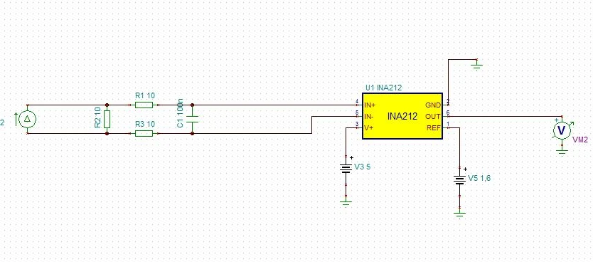
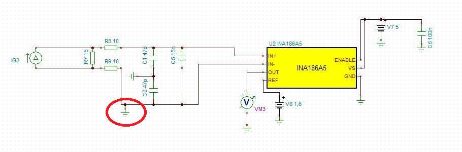
I'm studying this component to use with a current transformer to measure the current  through it. I simulate next circuit with the next considerations:

- I use an ideal operational amplifier to simulate INA213

 - I use a current source to simulate the secondary current produced by the current transformer. It is divided by 1000 becuase of the transformer has a relation of 1000:1. I want to amplify 22 mA.

 - R9 is 15 Ohm because of is the termination resistor of the current transformer I'm going to use.

 - I put Vref in the middle of the 3.3 V.

 - Also, I added C, R10 and R11 to decrease input bias current as the datasheet explain. (Pag 16 of datasheet)

My problem is I don't know if the Rshunt is so high and it could affect Vout. I can't reduce it because is the resistance that the datasheet of the current transformer specifies.

How I can model Input bias current to see its effect. Like a crrent source or a resistor...?

  • Hello user,

    We have models available for these devices that may help links below.  Adding resistors will not decrease the input bias current but could protect the input from voltage changes.

    Some information on IB.  https://training.ti.com/getting-started-current-sense-amplifiers-session-8-understanding-filter-related-errors

    We do have low IB devices for current sensing but they have different specifications and cost.  INA190, INA191, INA186

    Also can you attempt to import your schematics in another format as I cannot read it.

    Models (3)

    TitleCategoryTypeDate
    INA212 PSpice Model (Rev. A) PSpice Model ZIP 30 Sep 2011
    INA212 TINA-TI Reference Design (Rev. A) TINA-TI Reference Design TSC 30 Sep 2011
    INA212 TINA-TI Spice Model (Rev. A) TINA-TI Spice Model ZIP 30 Sep 2011
  • Hi,

    input bias current is modelled as shown below:

    Have you carried out a TINA-TI simulation? Can you give us your TSC-file?

    Kai

  • Hello Initial Poster, ,

    I assume we answered your question with the replies.  I will close the thread.  If you still need assistance please let us know.

  • Sorry, I was busy and I try this component in TINA to see how it works.

    In the first messasge, I can't add an image, so I am going to put a link to Drive with tre circuit and the simulation:

    I simulate next circuit with the next considerations:

    - I use a current source to simulate the secondary current produced by the current transformer. It is divided by 1000 becuase of the transformer has a relation of 1000:1. I want to amplify 10mA through the primary, who is 10uA through secondary.

     - R2 is 10 Ohm because of is the termination resistor of the current transformer I'm going to use.

     - I put 1.6V in Vref

     - Also, I added C, R1 and R3 to decrease input bias current as the datasheet explain. (Pag 16 of datasheet).

    In the simulation, I can see input bias does not affect Vout. Is this a real simulation? Have TINA considered in the simulation all paramethers,  input bias current included? Or it is an ideal simulation?

    Again, sorry for the delay.

  • Hello,

    I would not use the INA212 to measure µA of current.  I would steer you to the INA190 or INA186.  These devices have low input bias current.  Also in your simulations there is no common mode voltage at the inputs and that voltage is not defined.  You would need to bias it to some voltage.  You will see that then there is a current across the 10Ω resistors and that current will be larger than the current you are attempting to measure.  The current on each input pin will vary from also with input common mode voltage as seen in the datasheet in figure 11.  

    If the input bias current is larger than that of target of your measurement you can have issues.

  • Hi, thanks for your reprise,

    I understand that it's better use a current sense amplifiers that has less bias current than the current I want o measure and both you have recommended has low bias current.

    Aside of this, I don't understand when you say  " Also in your simulations there is no common mode voltage at the inputs and that voltage is not defined.  You would need to bias it to some voltage".  IN+ and IN-  is connected in parallel to  R2. The voltaje in R2 is 10 uA * 10 ohm = 0.1 mV,. The gain is 1000, so Vout is 0.1mV * 1000= 0.1 V. Because of the Vref is 1.6 V, the voltaje oscillates from 1.5V and 1.7V. So, I'm understand it is correct. Will you confirm it?

    Also, I simulate the nextcircuit with INA186 you recomended:

    I put C2,C1 and C5 as a filter I see in TIDA-00454 project.

    Vref is 1.6V and Vout is 10uA * 15 ohm= 0.075V, so Vout oscillates from 1.675 and 1.525V. It is correct?

    Could I amplify this circuit to adapt the voltaje to ADCs?

  • Hello,

    Regarding your question about no common mode you added a common mode voltage is that the input voltage is not controlled by any voltage.  This means it is not bias and can move away from the INA212 ground potential.  On your second circuit you limited your Voltage common mode to GND.  This forces the input voltage common mode to zero voltage.  Images of your schematic below and I circled the VCM you added to your INA186.  Your input bias current on your INA212 will be dependent on the VCM voltage.

    So the output voltage I calculate as  10µA * 15Ω = 150µV at the input of the INA186A5.  Then with a gain of 500 you should see a change of 75mV as you stated.  You must also be aware that the VOS of the INA186 is specified to 50µV so you will also could have an offset error of 25mV(50µV * 500) from your Vref voltage at your output.  If a DC offset is not important to you application then if will not matter.  

    For such low current measurements you may want to increase your Rshunt value.  If you add another gain stage please be aware of your offset errors  you introduce in the following stages.