This thread has been locked.

If you have a related question, please click the "Ask a related question" button in the top right corner. The newly created question will be automatically linked to this question.

LMC6482: Possible relative/absolute ground reference issue in TI LMC6482 Pspice model?

Part Number: LMC6482
Other Parts Discussed in Thread: LM358, TINA-TI

Hello,

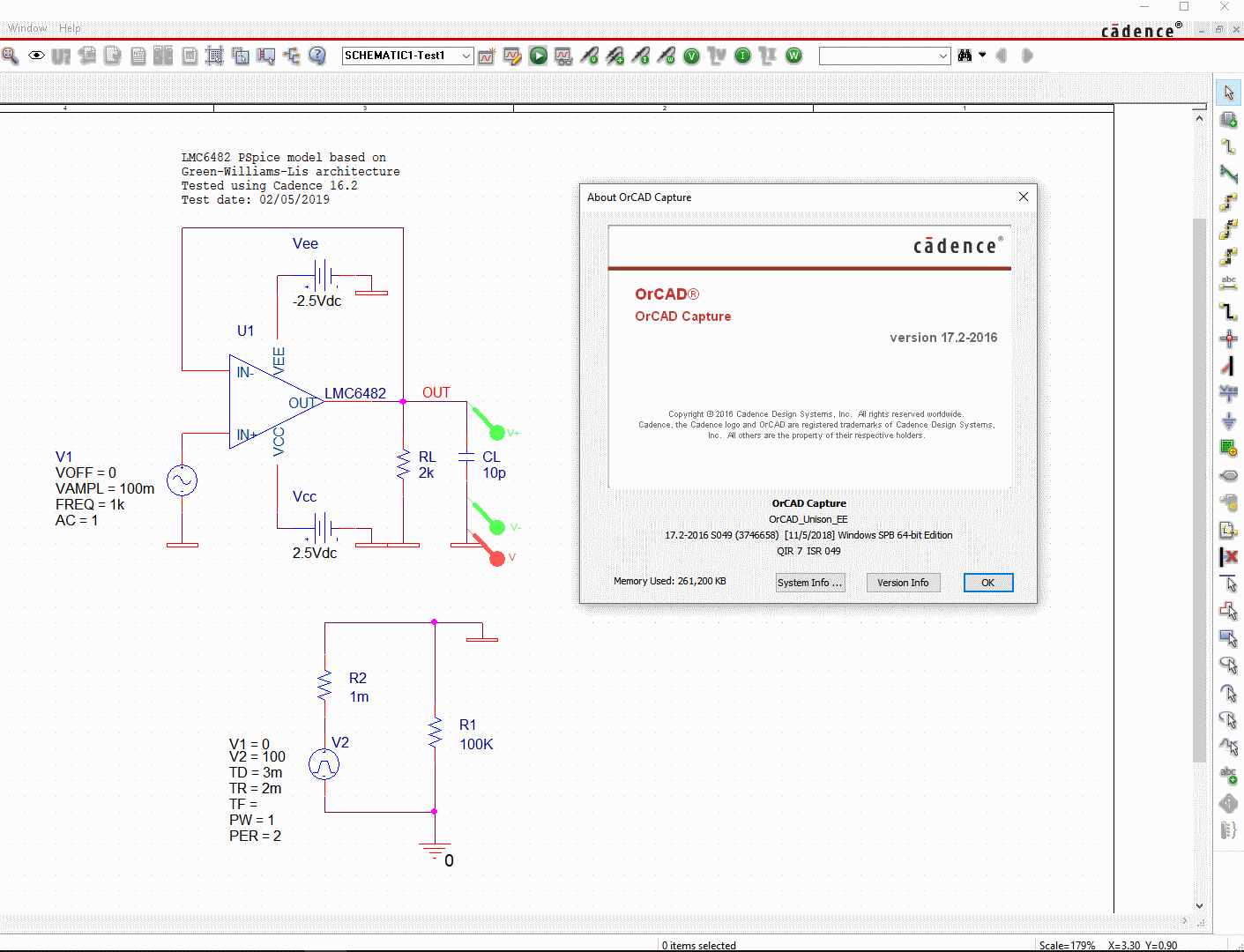
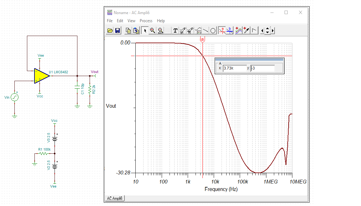
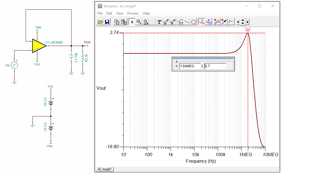
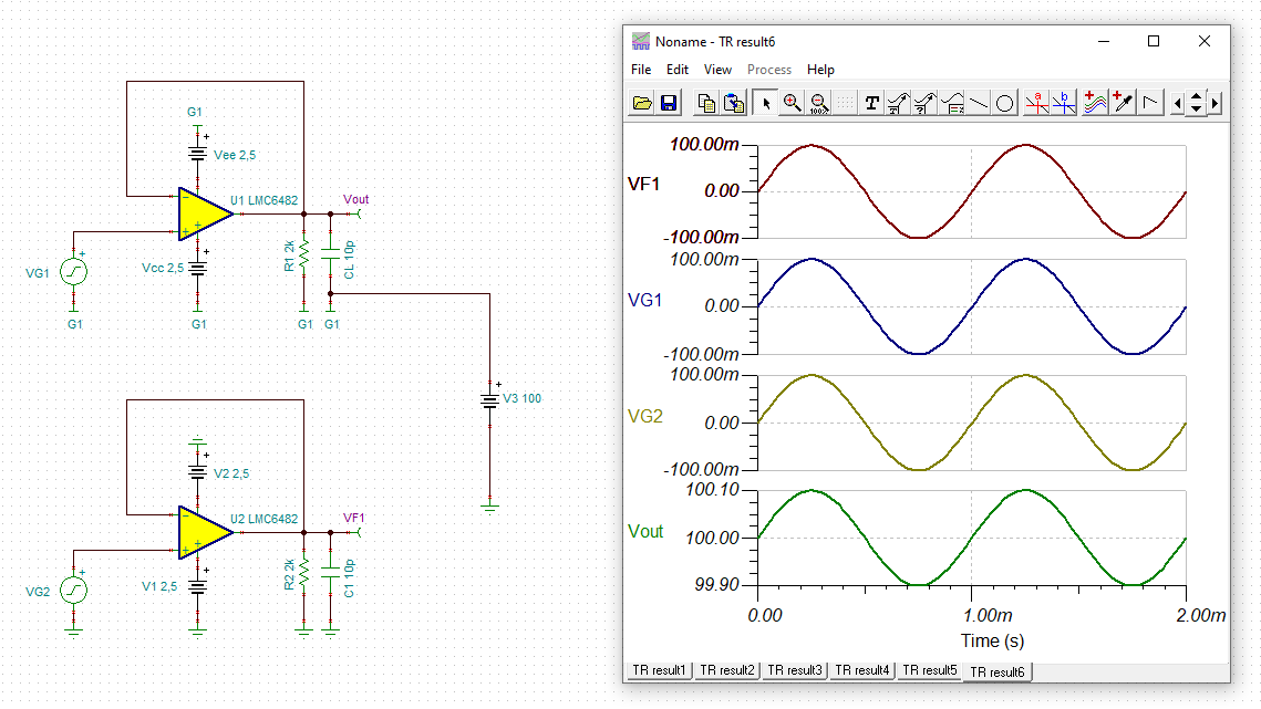
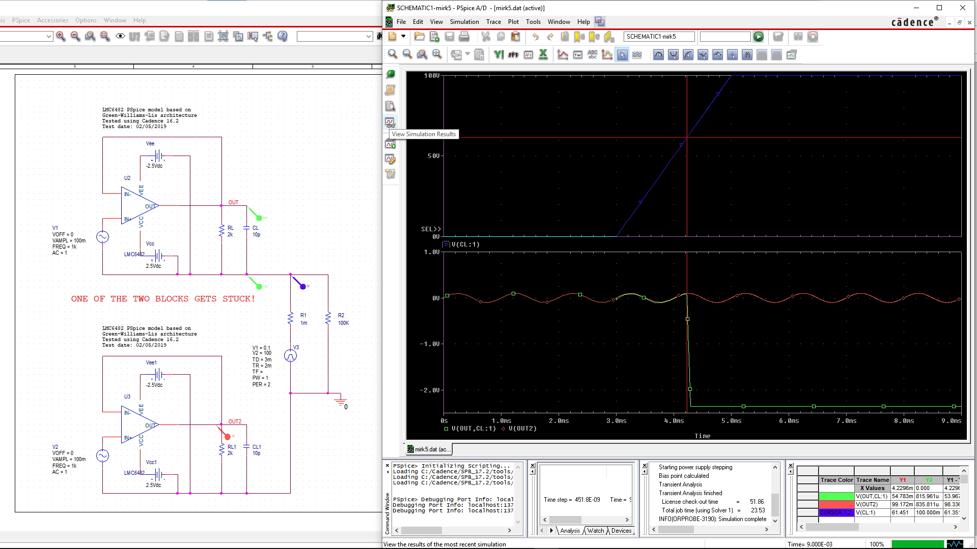
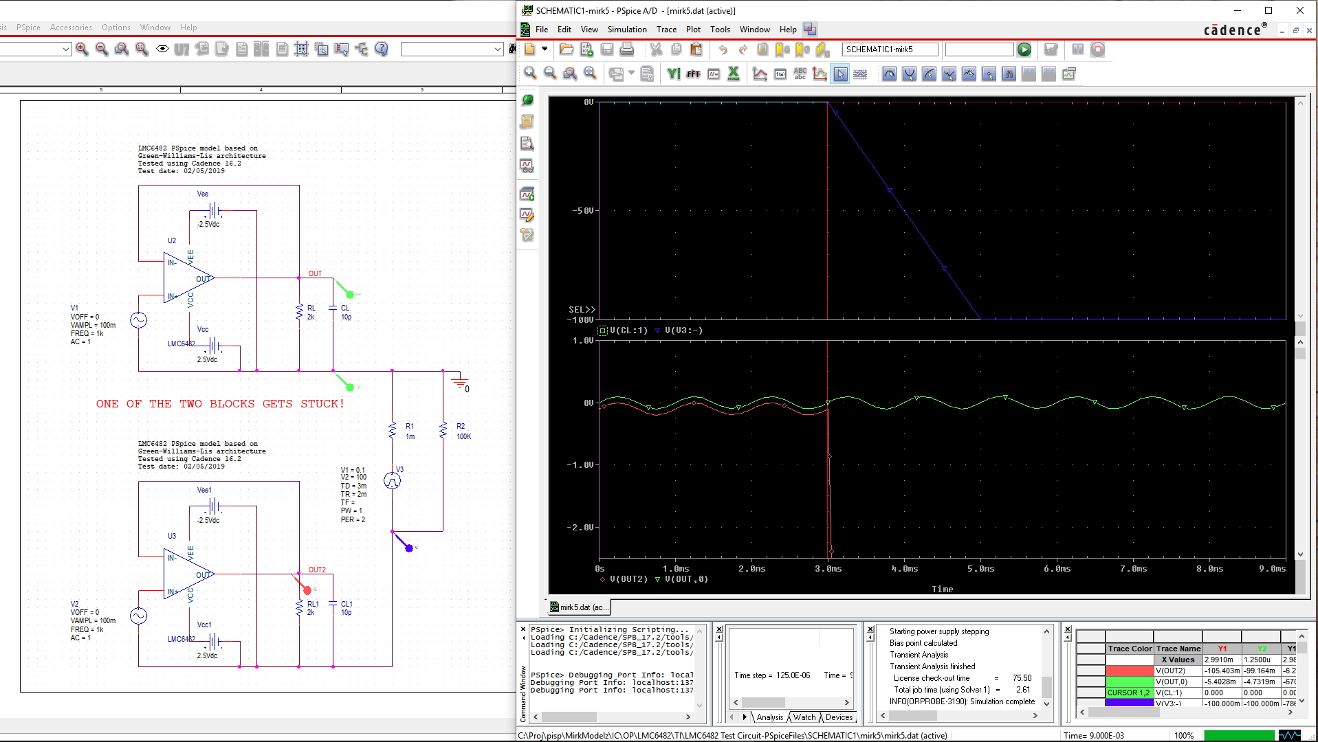
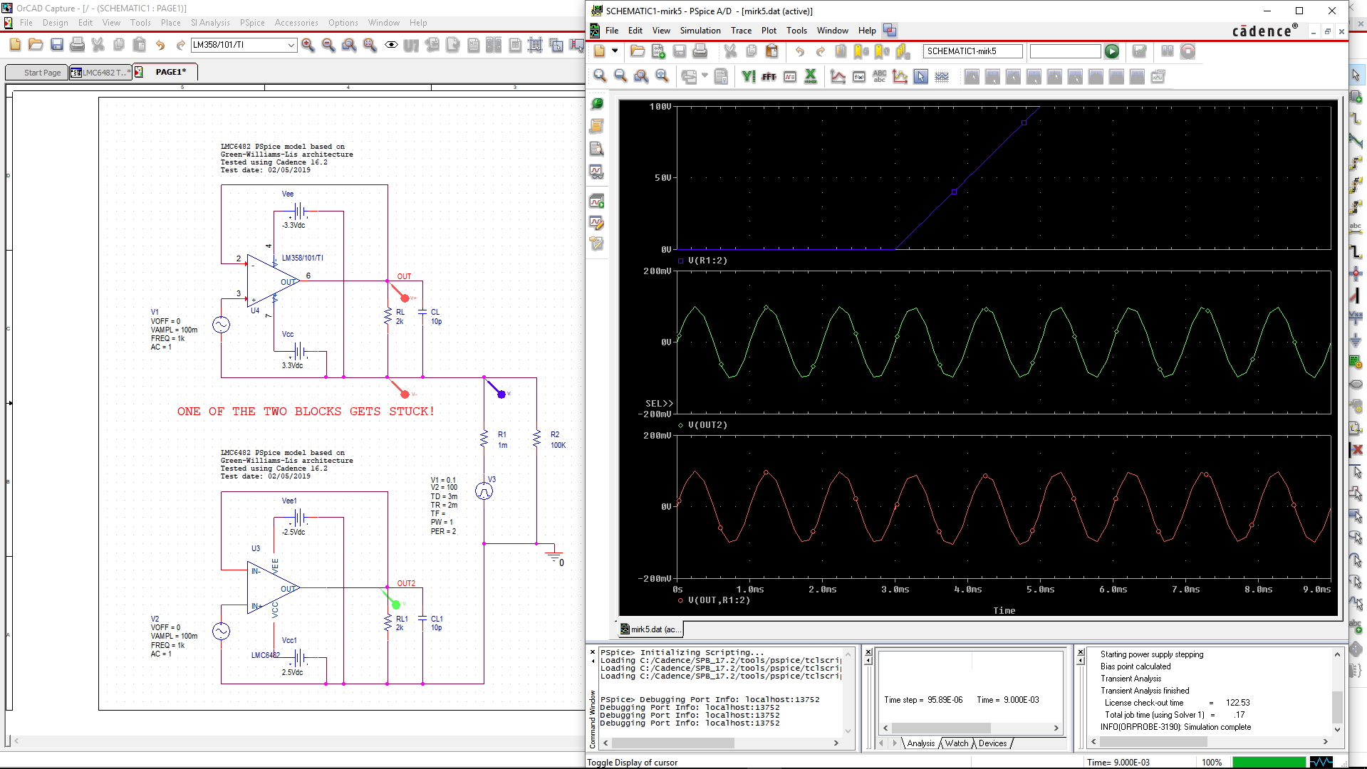
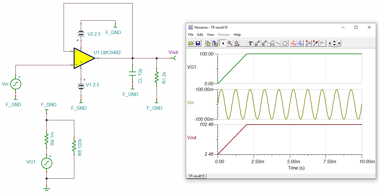
I would like to simulate the LMC6482 TI Pspice model in a complex schematic with various grounds; however, unlike several other OpAmp models I tried, looks like this model suffer (erratic output behaviour and/or stuck simulation) when "hung" on a ground reference far from the spice 0 ground (see picture).

Is there a fix other than placing the 0 ground directly as the OP Amp reference?

Thanks

  • Hi Mirko,

    Can you reload the picture? Somehow it can't be viewed. 

    I modified the reference design, and placed 100kOhm at the ground (simulate floating ground). I did not see any issues. Please let us know.

    Best,

    RaymondLMO6482 Ref. Ground.TSC

  • Hi Mirko,

    Currently, I do not have Cadence PSpice software, so I am unable to pin out your exact issues. However, I noticed something weird about your floating ground. 

    In V2 source of the simulation, 1mOhm is in series with V2 and parallel with R1, which is 100kOhm. V2 is a generator voltage source and its impedance is low (in an order of hundred milliohms or less) . If you want to have a floating ground, you may consider to place R1 (100kOhm) in series with V2 and R2(1mOhm). 

    Also, I noticed V2 has 100V pulsation signal acted upon the floating ground. You will need to filter out the pulsation signal on the floating ground, see the attached image below. With the presence of the pulsation signal, your common mode voltage at input may be outside of input range of the part.  

    With the attached Tina simulation, the configured LMC6482 has BW approx. 3.73kHz. I am not sure that there is enough BW for your application. 

    At the unity gain of LMC6482 in the above configuration without the floating ground, there is Que generated at approx. 1.84MHz. We need to find a way to compensate the gain peaking. Please let me know your design and application requirements. We can find a way to resolve the Que. 


    Best,

    Raymond

  • I apologize because of my poor description. I try to explain better my problem.

    I don't want a floatig ground. I have a situation where my op-amp sits on top of an high voltage (100V or more). In other words, none of the nets of the op-amp circuit have any galvanic connection (at least visible) to anything except its relative ground, wich in turn, sits 100V higher than the spice 0 ground. You can short the 1mOhm resistor and remove the 100K to make the schematic clearer. You could also replace the pulsed generator with a fixed 100V source. Now, there is apparently nothing strange in this connection, and I am pretty sure that in the real world it would work. I used a slow pulsed source to show that a certain point (when the local ground is far around 60V from the 0V spice ground) the op-amp gets stuck.

    Now: why if I swap the local and absolute grounds the simulation works, whereas if I take the TI op-amp reference schematic and add a 100V battery connected un just one side of the circuit,  like in my schematic, the simulation gets cheated?

    Note that if I replace the LMC 6482 with a common LM358, the simulation behaves well...

    Now, you could ask me why I am bothered to place the 0 ground at Op Amp side and live in peace... It's because I need to simulate a condition with two or more op-amps, working one on the bottom side of the circuit and on on the top side (without any other galvanic connection in common except one single point... Such simulation is unsuccessful with the actual LMC 6482 model, why?

    Regards

    Mirko

  • Ciao Mirko,

    in TINA-TI the simulation doesn't fail:

    mirko_lmc6482.TSC

    Kai

  • Hi Mirko,

    I downloaded the LMC6482 PSpice model from TI's website, and imported it to another simulation tool. I am able to simulate the circuit with 100Vdc offset from GND without any issues, which is shown the same results as Kai's simulation. So I have to assume that the PSpice model is likely good. 

    Best,

    Raymond

  • Hi Mirko,

    Can you simulate your top circuit on its own? Your top and bottom circuits are shared with the same OUT labels in both circuits. I am not sure that will make any differences. 

    Best,

    Raymond

  • Hi, thanks a lot to you all for your time and interest.

    Oops, of course the label duplication was a mistake. I enclose the simulation with correct labels; another with the zero connected on top side; and what happens with an LM358 on the far side.

    Bye

    Mirko

  • Hi Mirko,

    I simulated your latest pulsation ground circuit with LMC6482 in Tina, I do not see any issues. Also, you replaced LMC6482 with LM358  in the last circuit, and it appears that it is working. 

    When you encounter simulation issues, please simplify your simulated circuit. Please simulate one circuit at a time. Once they are working individually, then you combine these together. Also, please check that you do not have computer memory issues with  your tools? 

    Best,

    Raymond

  • Thank you Raymond, in my first pubblished simulation I am using just one Op Amp as given by TI ; I just added the 100V source, and it stops working...

    Yes, with the LM358 the circuit works...

    Regards

    Mirko

  • Hi Mirko,

    Can you send me the simulation that stopped working?

    Here is two simulations that I did yesterday. Both are working.

    Best,

    Raymond

    LMO6482 Offset GND 02052020.TSC

    lmc6482 100V ground 02062020.TSC

  • This is the PSpice simulation of the single high side OpAmp.

    Bye

    Basic.zip

  • Hi Mirko,

    I have to get back to you sometimes next week. I have to install Cadence Pspice software in my computer. With license and security requests at work, it does not happen immediately. 

    It is likely that you have Cadence Pspice simulation issues in the tool. I simulated several variations of your circuits (LMC6482 Pspice models) in two different PSpice tools without issues. Can you use Tina SPICE-based analog simulation program? It is free, see the link below. 

    Best,

    Raymond