This thread has been locked.

If you have a related question, please click the "Ask a related question" button in the top right corner. The newly created question will be automatically linked to this question.

AFE031: AFE031: signal distortion on powerline when current is needed from the PA

Part Number: AFE031

Hello,

We are having the exact same problem as this post :https://e2e.ti.com/support/amplifiers/f/14/t/723500?AFE031-signal-distortion

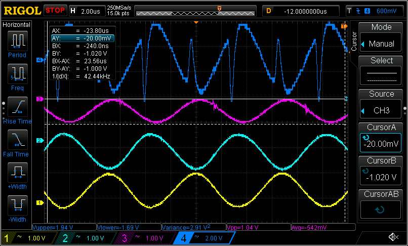
Here is our screenshot.

Ch1 : TP1 - PGAin

CH2 : TP2 - TX PGA-out

CH3 : TP11 - TX_F_Out

CH4: TP3 - PA_Out

We are using the BOOSTXL-AFE031-DF1 developpement board. We had to modify the PCB in order to be in "PWM mode" (I am actually using an external DAC connected to TX_PGA_IN). The modification is only to cut the trace going to ground on pin 16 TX_F_IN2. Without this modification there is no bias at the output of the filter when the TX block gets activated.

The distortion problem arise when we connect our line coupling system to the dev board (custom coupling transformer with 1.6 TX ratio). 

When we use only resistive charges without the powerline (connected directly to the BOOSTXL) the sinewave stays clean even down to 2 ohms load.

When connected to the powerline with our coupling transformer, if the "line load" is not to big (around 50 ohms at 144khz) the sinewave stays clean but when the line load gets a bit heavy (around 5-10 ohms at 144khz) then we get the distortion problem. In short, if the PA has to output a bit of current on the line it distort a lot.

It is not a problem of current flag or thermal flag (neither of those are triggered) has this was suggested by TI.

I will try with different inductive load an see if I can reproduce the problem without being connected to the powerline but I will be happy if anybody have any cue !

Thanks !

  • Hi William,

    When we use only resistive charges without the powerline (connected directly to the BOOSTXL) the sinewave stays clean even down to 2 ohms load.


    This means that the AFE031's power amplifier is working properly. 

    When connected to the powerline with our coupling transformer, if the "line load" is not to big (around 50 ohms at 144khz) the sinewave stays clean but when the line load gets a bit heavy (around 5-10 ohms at 144khz) then we get the distortion problem. In short, if the PA has to output a bit of current on the line it distort a lot.


    I need more load information from you (though I can extract some data from your plot). What is the output voltage swing? What is your output capacitance and inductance of your coupled transformer? Can you share the schematics with us, since you are using your custom coupling transformer with Primary:Secondary=1.6:1? Did you connect a load at the secondary winding? In addition, I want to calculate your transmission losses.

    Since you are using the custom transformer, please make sure that the transformer type is able to handle the 144kHz frequency with minimum coupling losses per PLC application, including the current load, 5-10 Ohm at 144kHz at the transformer. If you are not sure, please send me the coupling transformer data. 

    From the attached image, the ch4 is the output of PGA_OUT or pin 42/43 I am confused. The input to PGA_IN looks good, but the PGA_OUT signal does not look smooth with staircase characteristics + glitch/distortion.  The signal portion should look smooth (similar to input signal) at least, so I was wondering if it is mislabeled. 

    Enclosed is a copy of user guide. Please let us know. 

    sbou223 User Guide.pdf

    Best,

    Raymond

  • Hi Raymond,

    It turned out our custom transformer was the problem. This transformer has 3 windings : one for the line, one for RX and one for TX. I saw that when I shorted the RX windings while trying to transmit the problem got worse so it pointed out that the problem was there.

    I switched to a T60403-K5024-X044 which has only 2 windings and the distortion problem is now gone.

    I also did some other modification on the BOOSTXL :

    • -switched L1 inductor for one with a high current rating
    • -Changed C1 for a 1uF intead of 10uf
    • -removed R12 and R14 since we are injecting our RX signal directly at C8 (after passive RX filter).

    Thanks for your help Raymond ! (I know you also helped Jean-Christophe which is sitting two desk from mine :)