This thread has been locked.

If you have a related question, please click the "Ask a related question" button in the top right corner. The newly created question will be automatically linked to this question.

INA125: INA125 output without input

Part Number: INA125

Hi,

I'm using the INA125 to amplify a strain gauge. This is the schematic:

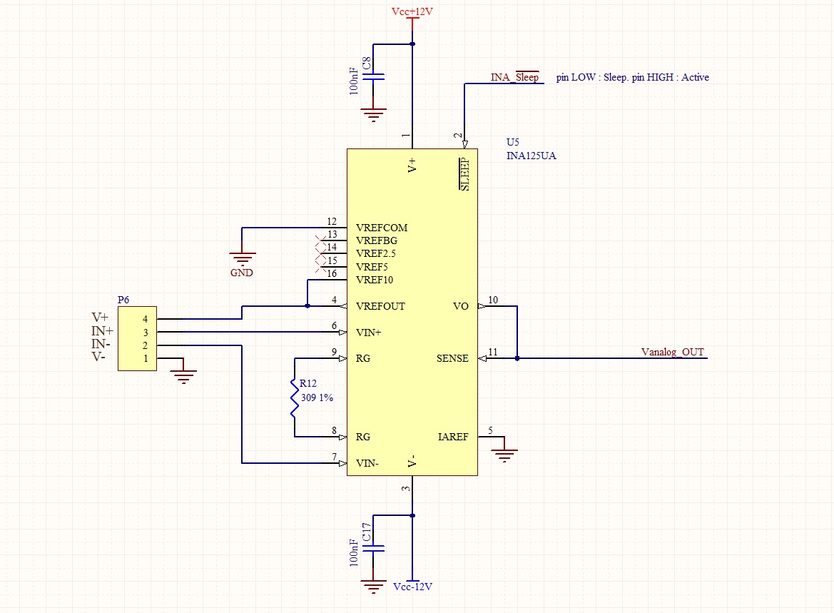
the output of the INA125 goes into an analog input of a microcontroller.
My problem is that when the strain gauge is disconnected, the INA125 output goes at +12V. How can I evitate this?

Thank you for your support.

Best Regards.

Giuseppe

  • Hi Giuseppe,

    The output transfer function is Vo=(V+ - V-)G. The circuit gain is G=4+60kOhm/309Ohm=198.18. If the output is 12V, the input difference is calculated to be 60.55mV (minimum). 

    Since both inputs are floating, the input voltage delta (V+ - V-) is not unreasonable (see the image below) . If you short the input terminal, you should get output voltage=0.  Also, this is a way to tell if the strain gauge is gone bad, if your output voltage is railed. 

    Best,

    Raymond

  • Hi Raymond,
    thank you for reply.
    In my project the strain gauge can be disconnected by the device because it's connected to him by a connector. When this happen I've the problem. Then you tell to add 2 pull down resistor to the two inputs? In this way the measure when the strain gauge is connected can be influenced? What is a good value of the pull down resistors?
    Than you.
    Giuseppe

  • Hi Giuseppe,

    One easy solution is to use the uC to put the INA125 into sleep mode before disconnecting the gauge, then take it out of sleep mode after the gauge has been reconnected. Of course, if the disconnection of the gauge cannot be anticipated, this won't be so simple.

    Alternatively, in accordance with Raymond's suggestion, you can add some very weak pull-downs at the inputs, so that when the gauge is disconnected they both go low. See Figure 3 of the datasheet.

    Cheers,

    Jon

  • Hi Jon,
    unfortunately the disconnection of the strain gauge can't be detected by the uC. What is a right value of the pull downs? In the figure 3 there isn't an example with the strain gauge.
    Best Regards.
    Giuseppe

  • Hi Giuseppe,

    What is the output voltage range vs. input signal of your circuit? What was your problem when the output voltage is railed for your uC?  Can you send me the input strain gauge circuit (values of resistors), and I will figure out a solution?

    Best,

    Raymond

  • Hi Raymond,

    usually I use a strain gauge of 2mV/V with resistors of 300ohm or 500ohm. The output voltage range is from 0 to 3.3V.

    Best Regards.

    Giuseppe

  • Hi Giuseppe,

    I suggested to use 300kOhm pull down on both sides of input. The error of the modification is about +/-0.1%, which is within the range of the Gain error. 

    If you do not like the solution, you may place a zener at the output of INA125 output, so that INA125's output voltage will be clamped not greater than zerner voltage. 

    Please let me know if this works for you.

    Best,

    Raymond