This thread has been locked.

If you have a related question, please click the "Ask a related question" button in the top right corner. The newly created question will be automatically linked to this question.

LMH5401: Seeing 0.5V difference between Vocm on +/- outputs

Part Number: LMH5401
Other Parts Discussed in Thread: ADS54J60,

Hi all,

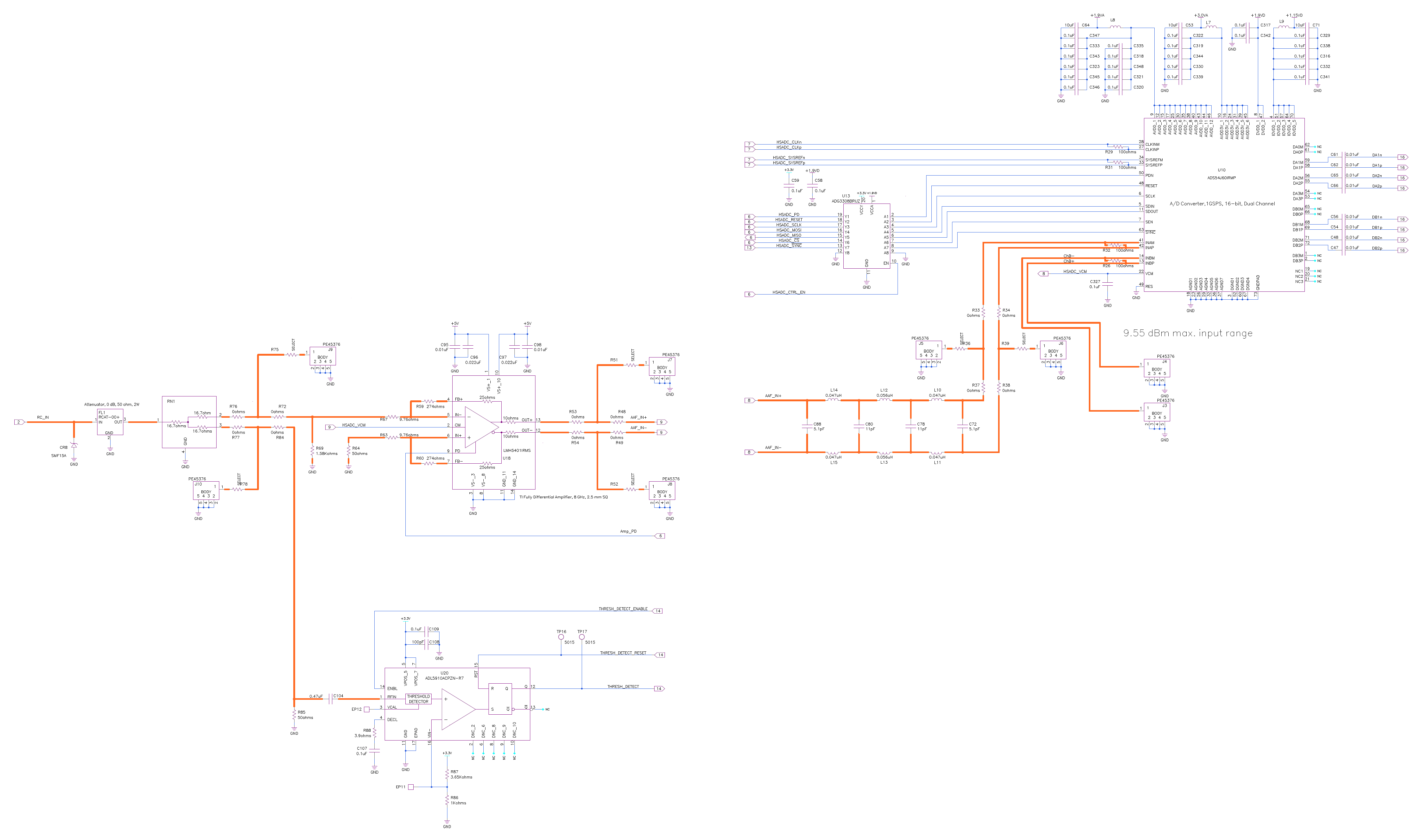
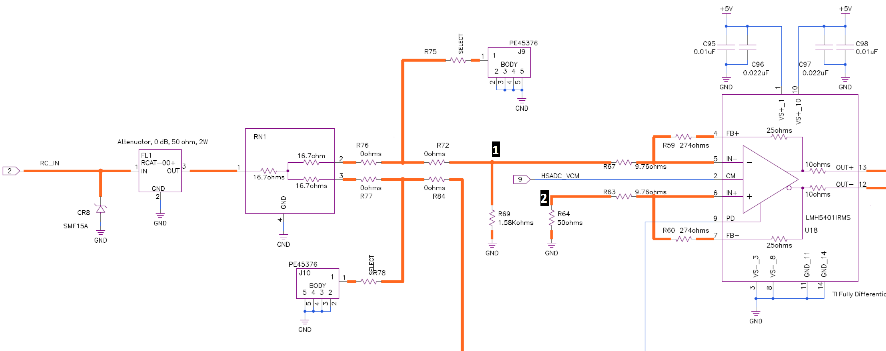
I have a board with an LMH5401 interfaced to a ADS54J60. We've tied the ADS54J60 VCM output to the LMH5401 CM input with a 0.1uF bypass cap.

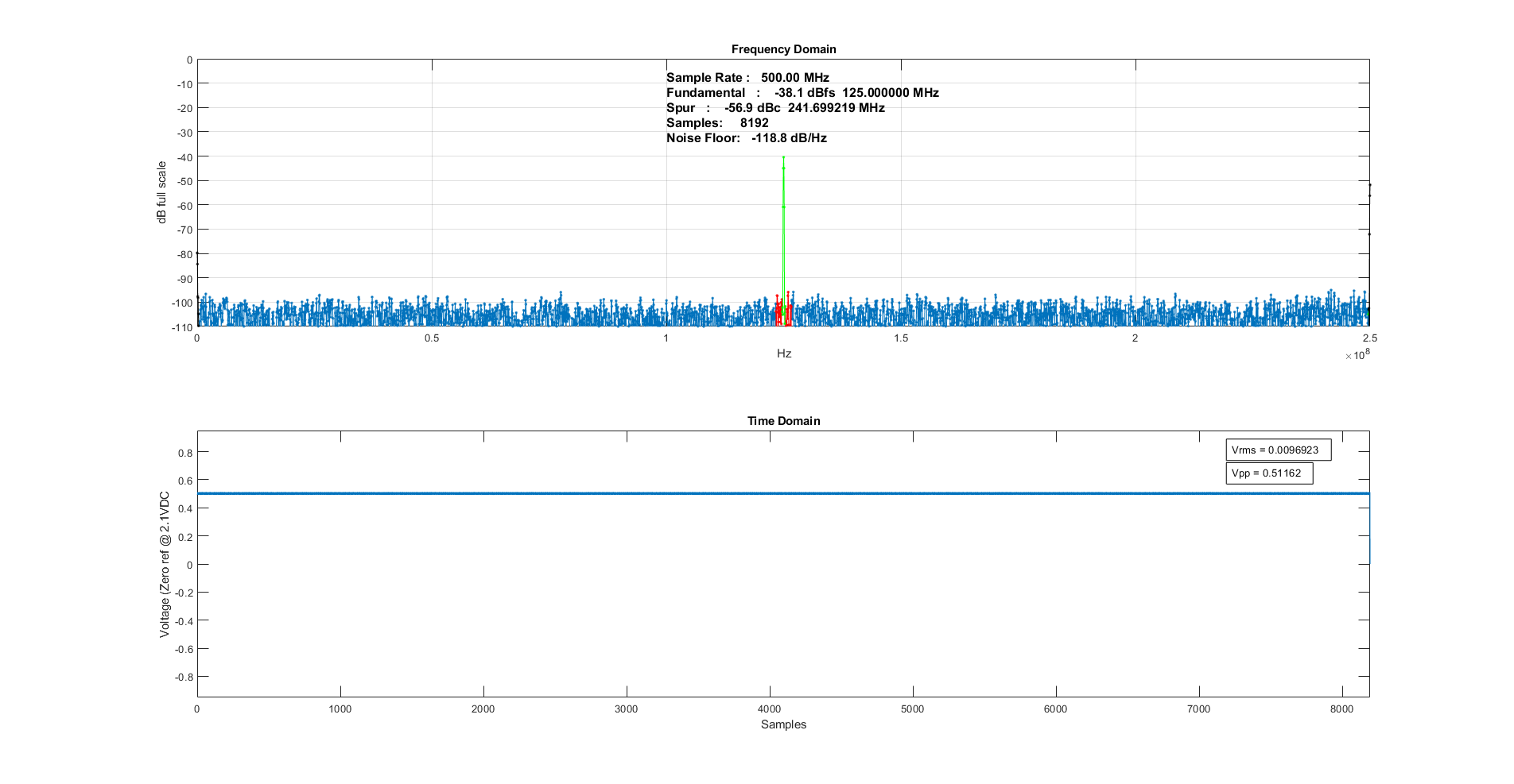
Measuring at the amplifier, I read 2.1V at the CM input, which is what I would expect, but OUT+ measures 2.3V and OUT- measures 1.8V. Same when I measure at the INAM and INAP pin on the ADC.

  • Hello Charles,

    Based off of your values, you are getting an output common mode of 2.05V. It is possible that the VOCM gain of your amplifier is on the lower end at 0.98 V/V (shown on page 7). It seems like the main issue is you are getting a differential output of around 250mV while not expecting one? Can you share your schematic? Are you providing an input into the LMH5401?

    Best,

    Hasan Babiker

  • Hi Hasan,

    I'm seeing about a 0.5 volt offset in the output data with no input signal to the ADC (along with a spur at Fs/4):

    When I input a signal with a Keysight N5181B, the offset remains the same. Here's the schematic:

  • Hello Charles,

    Can you measure the voltage that is being seen at R69? Also, both sides of your FDA need to be identically matched. This means that R64 needs to be set to the parallel combination of R69 along with all preceding resistors. Please confirm that you are measuring the same resistance across both resistors. 

    Best,

    Hasan Babiker

  • Hi Hasan,

    Thanks for the reply! I took some measurements.

    I measured at R69 (node marked 1) and read 365 mV. I measured at R64 (node marked 2) and read 333 mV.

    I measured resistance at node 1 and node 2 wrt to ground and read 72 ohms and 47 ohms, respectively.

    I also measured a few other voltages at the LMH in case it helps: pin 4 1.62V, pin 5 400 mV, pin 6 400 mV, pin 7 2.22 V

  • Hello Charles,

    The fact that nodes are reading almost the same voltage indicates that you are not inputting a differential signal. This confirms that the issue is due to resistor mismatch. I recommend either changing R69 to around 125 ohms or R64 to around 79 ohms. 

    Best,

    Hasan Babiker 

  •  Thank you Hasan. That fixed it. How did you determine those resistor values?

  • Hey Charles,

    Glad to hear that it worked!

    I first used the resistances that you measured to figure out how much resistance was in parallel to R69 & R64 (for example: 1.58k would need to be in parallel with 75.44 ohms in order to get a total combination of 72).

    From there you can use that value to figure out what you would need to get the same total resistance on the other side (so 75.44 ohms would need around 125 ohms in parallel to get a total resistance of 47 ohms).

    Best,

    Hasan Babiker

  • Hi Hasan,

    Okay great, that's pretty straightforward! Thanks again for the help. It also removed the Fs/4 spur. I'm a happy camper :D