This thread has been locked.

If you have a related question, please click the "Ask a related question" button in the top right corner. The newly created question will be automatically linked to this question.

XTR111: Input Referred Noise Spectrum

Part Number: XTR111
Other Parts Discussed in Thread: TIDA-01471, DAC5311, OPA2197

Hi

We would like to use the XTR111 as part of a programmable current source foe use with IEPE sensors, as described in TI's TIDA-01471 IEPE Vibration Sensor Interface for PLC Analog Input Reference Design. The IEPE circuit in the reference design is basically what we need.

Looking through the datasheet for the XTR111 I have once concern. Figure 6 of the datasheet shows a graph of the Input-Referred Noise Spectrum. There are a number of noise spikes at frequencies of 10kHz, 20kHz.. 50kHz, due, I understand, to the chopping nature of the current source in the XTR111. Our application requires an analog bandwidth of 20kHz & so I am concerned that some of this noise might appear in the signal path from the IEPE sensor.

Figure 6 shows the noise as a voltage, typically 10uVrms RTI when I=2mA. How do I relate this noise voltage to the output current from the XTR111/External PNP transistor? We plan to use the DAC5311 as per the reference design and design for  0 to 3V == 0 to 20mA. Do these spikes increase with current?

regards

Steve

  • Hi Stephen,

    have you read the section "Dynamic Performance" of datasheet?

    Kai

  • Hi Kai

    It looks like the XTR111 is quite noisy so. I am considering using a modified version of the verified design SLAU502 instead. I have simulated in TINA a 0 to 3V input, 0 to 20mA output using the OPA2197 & the results look good to me. Do you think this would be a good approach for biasing IEPE sensors or do you see any pitfalls with this circuit?

    regards

    Steve

  • Hi Steve,

    If we can minimize the gate capacitance and filter 10kHz and 20kHz noises, you should be able to get rid of the current spikes. Majority of noise spectrum is a random noise except 10kHz and 20kHz, however these current glitch can be attenuated with low pass filters. 10kHz noise has 100 usec sampling period and 20kHz has 50usec sampling period. 

    I am wondering what are typical vibration characteristics in frequency distribution and amplitudes in your  sensor application. Let me do some simulation and make sure there will not be surprises.  . 

    Best,

    Raymond

  • Hi Raymond

    The current source is for use in a new product (there will be 8 identical channels per device). The customer has specified IEPE sensors, with an analog bandwidth from 0.5Hz to 20kHz. Hence my concern about the 10kHz/20kHz spikes. The current source provides biasing for the IEPE sensor. But of course IEPE is a 2-wire interface so that the signal sits on the bias level before being AC coupled.

    regards

    Steve

  • Hi Steve,

    What is your supply voltage rail? I have something working. In addition, I imported a low input capacitance Mosfet (DMP21D6UFB4, 55.4pf), though the Vds voltage ratings are not optimized. Anyway, I will take care of this on Monday, and find a way to simulation current glitch at 10kHz and 20kHz.

    What was the acceptable current errors in your application, +/- 0.1%?

    XTR111_0_3V_to_4-20mA noise injection 02152020.TSC

    Best,

    Raymond

  • Hi Steve,

    You made the following comments:

    The current source provides biasing for the IEPE sensor. But of course IEPE is a 2-wire interface so that the signal sits on the bias level before being AC coupled.


    Is the 0-20mA current source is DC biasing for the IEPE sensors? If this is the case, you do not have issues at all (it can be easily filtered out). Please let me know. 

    I will show you the current glitch simulation on Monday. 

    Best,

    Raymond

  • Hi Raymond

    Yes, the current source is for biasing IEPE sensors. See TIDA-01471 http://www.ti.com/tool/TIDA-01471

  • Hi Stephen,

    yes, the 10kHz, 20kHz, 30kHz, ... noise peaks shown in figure 6 of datasheet of XTR111 will considerably increase the output noise of XTR111, as can be seen from figures 39, 40 and 41 in section "Dynamic Performance" of datasheet. But, how much this noise will degrade the signal to noise ratio of signal chain mainly depends on the output impedance of IEPE sensor. An AC output impedance of 0R would totally suppress the noise of XTR111. And the higher the output impedance of IEPE sensor is, the worse will be the signal to noise ratio.

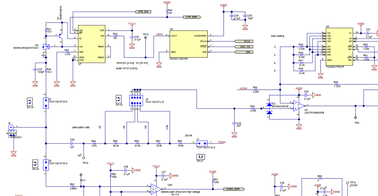
    Noise filtering is not that simple, because the XTR111 circuitry must maintain a high impedance to the IEPE sensor. Remember that an ideal current source has an infinite output impedance. So, the filtering cap at the output of XTR111, needed for dampening the noise peaks, must not create a too low impedant path to signal ground, because this would also cause a dampening of wished signal in this frequency range. That's why a very small C33 was chosen:

    100pF presents an impedance of about 80k at 20kHz, which seems acceptable regarding the signal frequency response. But 100pF has nearly no noise dampening effect. 10nF as recommended in the datasheet of XTR111, on the other hand, would present an impedance of about 800R at 20kHz, which is way too small for a signal frequency range of up to 20kHz. Again, this also depends on the actual output impedance of IEPE.

    Kai

  • Hi Kai, Raymond

    Raymond, my last response to you was cut-off for some reason after the hyperlink. The bias voltage is 28V.

    The customer has a specification of input impedance of 1M/1nF so I am indeed limited. The design has built-in filters at a number of frequencies up to 20kHz (again customer specified) so for lower bandwidths the circuit would behave well. It looks like there is simply a degradation in performance at higher frequencies. I considered LC filtering but am not convinced it would work well.

    I would value your opinion on a modified version of the TI verified design SLAU502, High Side Voltage to Current Converter.  I modified the design and simulated a 0 to 3V input 0 to 20mA output & it seems to work quite well.

    regards

    Steve

  • Hi Steve,

    You indicated that The bias voltage is 28V. Do you mean the supply voltage rail is 28? Is 1M/1nF input impedance is the AC coupled Op Amp specification for vibration sensor's input signals? What is the impedance of vibrational sensor?

    The current noise spikes in XTR111 are from the chopper amplifier. Since this is for Piezoelectric/Accelerometer application, the amount of filtering is somewhat limited. I am trying to find a best way to simulate the issues, and I came up with the following simulation model, see the attached file. The values of simulation is not finalized, and you can modified it as needed. 

    For the constant current drive, say constant current is fixed at 4mA as an example, and DC bias voltage is set at 10V, which the sensor's R load is 2500 Ohms. I arbitrarily selected 10uVpp noise in 10kHz and 20kHz bands, and simulate the vibration sensor with 10Vdc bias. 

    Alternatively, we may be able to place LC filter before the vibration sensor, and limited the BW at about 5kHz, then it will filter out (attenuate) the 10kHz and 20kHz current spikes. I can try out this approach, if you are interested. I need to know what is maximum capacitance coupling to ground per the design specification. What is your current accuracy specification?

    XTR111 Current Glitch Simulation 02172020.TSC

    Best,

    Raymond

  • Hi Raymond

    Yes, the supply voltage rail for the XTR111 is 28V.

    The customer requirement for the input impedance of the instrument we are designing specifies an Input Impedance of greater than 1M shunted by 1nF so I guess they mean greater than 1M resistance and less than 1nF capacitance.

    We don't know anything about the actual IEPE sensor9s) used. There is probably more than one. Typically the impedance is low, 100R to ~300R.

    My thought with an LC filter was to place it at the output of the current source. Consider Figure 2 of TIDA-01471. I am wondering whether an LC filter at the 'Program Current' location output would work. The excitation requirement is for DC current and if the spikes could be eliminated before reaching the Sensor/Input T-point then the problem would be solved. But I think the inductors might be too large. A quick calculation shows that 1mH/1uF would give a cut-off frequency of 5kHz. I am not convinced that this approach will work.

    Thanks to you & Kai for all your help on this btw.

    regards

    Steve

  • Hi Steve,

    Yes, we are greatly appreciative Kai's technical expertise and supports in the forum. 

    Regarding to IEPE sensors, there are many manufactures in making the vibration sensors. I have used several vendors of the piezoelectric sensors, and they all have different frequency response ranges, sensitivities, temperature ranges, single or multiple axis and other characteristics. 

    The constant current source is to set DC bias of these sensors to approx. mid point of voltage supply rails in order to maximize the AC voltage swings that generated from the Piezoelectric effect (AC voltage response vs. vibration, which voltage response will be analyzed via FFT algorithm to extract frequency components). Since many of IEPE sensors are low in impedance design, the stable constant current sources from 0-20mA will be necessary for the application. 

    Regarding the LC attenuation suggestion, it may not work as you pointed out. I realized that the Op Amp chopping or switching effects are more "mechanical" in nature, rather than sinusoidal type. In addition, large inductor size may be a required, though it may not be too large. Anyway, the another method to get rid of current glitch is to use notch filter to remove the characteristics frequency in the circuit. I figured that you may already have a working solution in this. 

    Best,

    Raymond