This thread has been locked.

If you have a related question, please click the "Ask a related question" button in the top right corner. The newly created question will be automatically linked to this question.

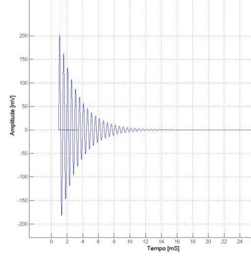
converting a low amplitude damping sine wave to an amplified square wave using multiple op-amps

Other Parts Discussed in Thread: OPA141

Dear All,

I'm looking for a circuit to be capable of converting a low amplitude damping sine wave to an amplified square wave so that I can measure its frequency using my MCU. The frequencies to be measured are usually in a range of 100Hz to 10kHz and Also, I prefer using +5V for VCC and GND for VEE.

  • Hi Reza,

    this is usually done by the help of a comparator.

    Is the starting amplitude always 200mV?

    Kai

  • Hi Kai,

    Thanks for your response. Actually, the starting amplitude is not always 200mV but it is in this order. It would vary from 50mV up to 250mV in different cases. Also, I know that this process can be done using series of OPA141 op-amps but I don't know how.

    Reza

  • Reza

    The basic circuit that you would require in an inverting amplifier configuration where you set the common mode to VS / 2.  The gain of the inverting amplifier would be determined on the max input voltage value.  For example, you provided a max value of 250mV (pk), assuming a 5V supply, that could theoretically get gained up by a factor a 10x and drive all the way to the power supply rail.  While many amplifiers claim that they can drive to the rail, there will be some distortion if you try.  So you may need to experiment with a gain of 8x to 10x.  The output of the inverting amplifier will be connected to the inverting pin of the comparator and the common mode voltage of VS / 2 is connected to the non-inverting pin.  At some point the dampened sine wave will get too close to the reference voltage of VS/2 and the comparator's integrated hysteresis will prevent the output from switching further.

    You didn't provide any performance target or budget for your circuit.  I have provided a relatively low cost option for you in the attached TINA schematic.

    Hope this helps get you started.

    Chuck

    For some reason I am having trouble uploading the TINA file.  I will try again when I re-post.

  • Dear Chuck,

    Really thanks for your answer. You've helped me a lot. I am looking for the highest possible performance so the required budget would not be a problem. Would you please try again to send me your TINA schematic?

    Regards,

    Reza

  • Dampening Sine Detect.TSC

    Sorry Reza

    I thought it went up on my last attempt.

    Chuck

  • Great!!! Thank you very much for your answer and support.

    Regards,

    Reza